
Bottom yarn beating device of spinning machine

A technology of spinning machine and bottom yarn, which is applied in the direction of manipulator, textile and papermaking, program-controlled manipulator, etc. It can solve the problem that the precision of time and position is very high, does not meet the direction of mechanization, and affects the success rate of bottoming yarn, etc. problem, to achieve the effect of wide range of use, simplified structure, and gentle turning out action

Pending Publication Date: 2020-05-05
AVIC SHAANXI HUAYAN AERO INSTR
View PDF0 Cites 0 Cited by
  • Summary
  • Abstract
  • Description
  • Claims
  • Application Information

AI Technical Summary

Problems solved by technology

[0003] To replace the bobbin by the cam linkage mechanism, the bobbin needs to be clamped by the mechanical arm composed of the linkage mechanism, and then the mechanical arm rotates around the axis to supply the bobbin between the two arms of the creel. The mechanical arm passes through two pairs of parallel mechanical fingers. When holding the bobbin, the bobbin and the mechanical finger will be misaligned due to vibration during the rotation of the mechanical arm, so that the bobbin cannot be smoothly clamped by the creel when it enters between the two arms of the creel, which affects the success rate of the bottoming yarn
[0004] The disadvantage of the existing cam-link mechanism still exists in that the cam-link mechanism needs five manipulators to cooperate to complete the actions of bobbin clamping, mechanical arm turning, yarn guiding, yarn cutting, and friction driving to complete a bottoming yarn. Among them, yarn guiding, yarn cutting, and friction driving are three independent manipulators, and the time and position accuracy requirements of mutual coordination are very high. The deformation of structural parts and the flexibility of moving parts will cause the failure of the bottoming yarn. , manual replacement of empty bobbins is time-consuming and laborious, does not conform to the direction of mechanization and has certain potential safety hazards

Method used


Image

  • Bottom yarn beating device of spinning machine
  • Bottom yarn beating device of spinning machine
  • Bottom yarn beating device of spinning machine

Examples


Embodiment Construction

[0045] In order to make the purpose, technical solutions and advantages of the embodiments of the present invention clearer, the technical solutions in the embodiments of the present invention will be clearly and completely described below in conjunction with the drawings in the embodiments of the present invention. Obviously, the described embodiments It is a part of embodiments of the present invention, but not all embodiments. Based on the embodiments of the present invention, all other embodiments obtained by persons of ordinary skill in the art without creative efforts fall within the protection scope of the present invention.

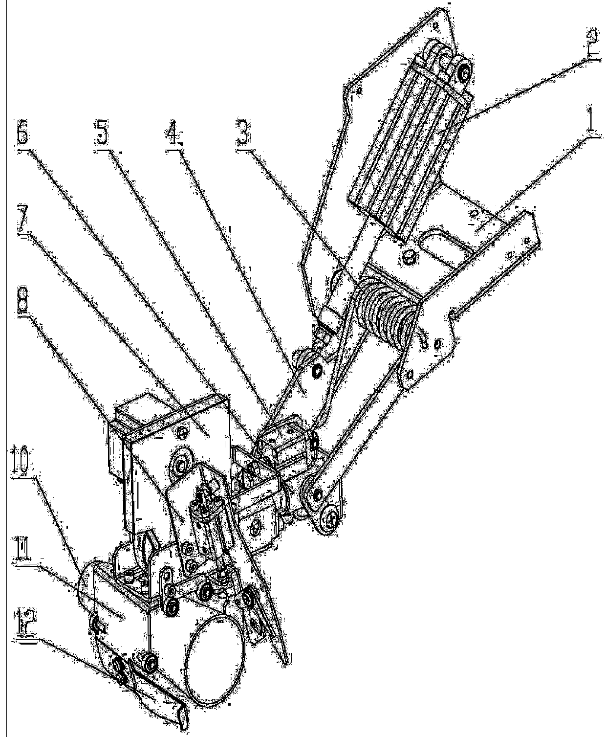
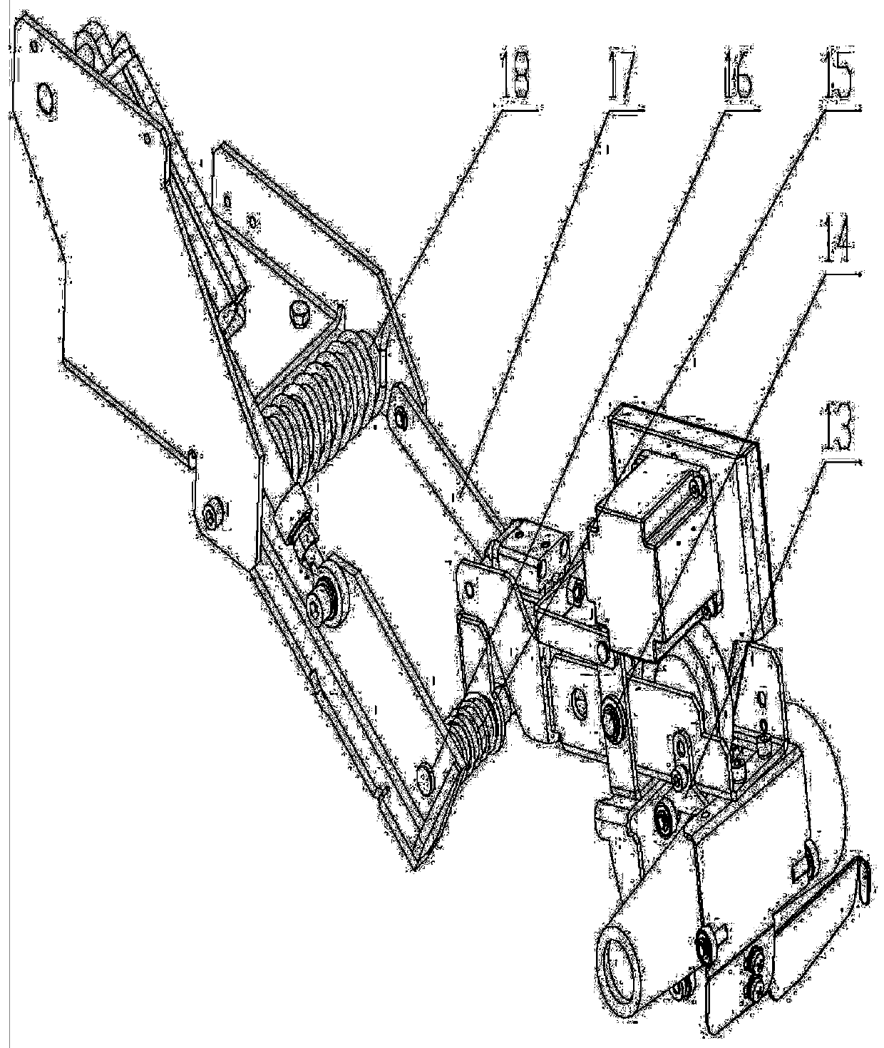
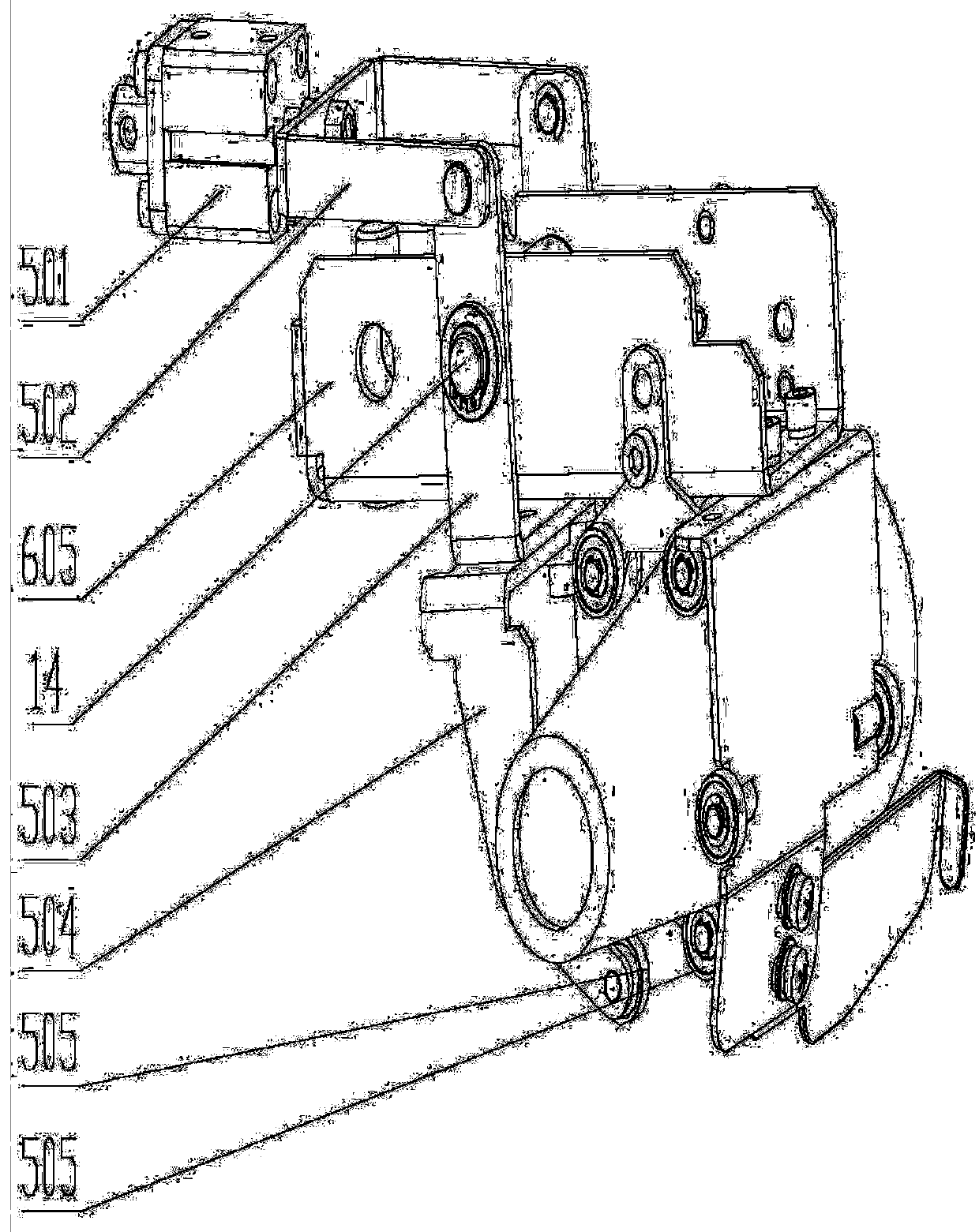
[0046] In view of the above-mentioned defects in the background technology, the present invention provides a spinning machine bottom yarn device, which includes a mounting base 1, a turning drive cylinder 2, a turning arm 4, a bobbin clamping assembly 5, a mechanical arm 6, a bottom yarn The drive assembly 7, the yarn end cutting assembly 8 and th...


PUM


Abstract

The present invention provides a bottom yarn beating device of a spinning machine. The device comprises a mounting base, a turnover driving air cylinder, a turnover arm, a bobbin clamping assembly, amechanical arm, a bottom yarn driving assembly, a yarn head shearing assembly and a bottom yarn guide plate; when a bottom yarn is beaten, the turnover driving air cylinder provides power for a turnover part in a defined space, a bobbin clamping part clamps a bobbin, excess waste yarns are sheared by a yarn head shearing part after the bobbin and the yarn reach a predetermined position, only the yarns in the direction of a spinning apparatus are remained when a bottom yarn driving part drives the bobbin to rotate, and the yarns are controlled to perform bottom yarn winding on the bobbin, thereby realizing bottom yarn beating of the spinning machine. Compared with the prior art, the requisite multiple procedures in the bottom yarn winding process are reduced, the equipment structure is simplified, the equipment cost is reduced, and the bottom yarn beating process is simplified.

Description

technical field [0001] The invention belongs to the field of textile machinery, and in particular relates to a bottom yarn device for a spinning machine. Background technique [0002] During the spinning or doffing process of the spinning machine, the capacity of the single-spindle yarn roll reaches a certain limit, and the empty bobbin needs to be replaced, and the newly generated yarn is wound on the bobbin to continue spinning. At present, the grounding yarn is usually completed by a cam linkage mechanism or manual operation. [0003] To replace the bobbin by the cam linkage mechanism, the bobbin needs to be clamped by the mechanical arm composed of the linkage mechanism, and then the mechanical arm rotates around the axis to supply the bobbin between the two arms of the creel. The mechanical arm passes through two pairs of parallel mechanical fingers. When holding the bobbin, the bobbin and the mechanical finger will be misaligned due to vibration during the rotation of...

Claims


Application Information

Patent Timeline
IPC IPC(8): D01H9/04D01H9/16B25J9/00B25J15/02
CPCB25J9/0009B25J15/0206D01H9/04D01H9/16
Inventor 代明赵明凯肖健营陈文国
Owner AVIC SHAANXI HUAYAN AERO INSTR
Learn More