Dual-drive turbine

A dual-drive, turbine technology, applied in engine components, combustion engines, machines/engines, etc., can solve the problems affecting the working efficiency of the supercharger and the low airflow passing efficiency.

Inactive Publication Date: 2020-05-05
车行天下网络科技股份有限公司
View PDF6 Cites 2 Cited by
  • Summary
  • Abstract
  • Description
  • Claims
  • Application Information

AI Technical Summary

Problems solved by technology

[0004] The purpose of the present invention is to provide a dual-drive turbine, aiming to solve the above-mentioned problem in the prior art that the two-channel airflow and the junction of the blades in the existing turbine confluence to form turbulent flow and the airflow passing efficiency is not high, which affects the working efficiency of the supercharger. Technical problem, a dual-drive turbine has the advantages of compact structure, convenient manufacture, and strong power, which can improve the working efficiency of the turbine and the driving force of the turbocharger

Method used


Image

  • Dual-drive turbine
  • Dual-drive turbine
  • Dual-drive turbine

Examples


Embodiment Construction

[0023] The technical solutions in the embodiments of the present invention are clearly and completely described below in conjunction with the accompanying drawings in the embodiments of the present invention. Obviously, the described embodiments are only part of the embodiments of the present invention, not all of them. Based on the embodiments of the present invention, all other embodiments obtained by persons of ordinary skill in the art without making creative efforts belong to the protection scope of the present invention.

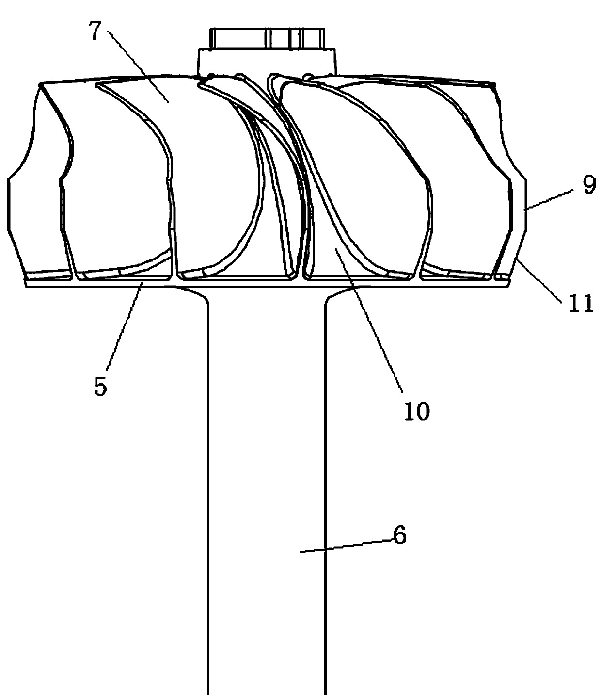
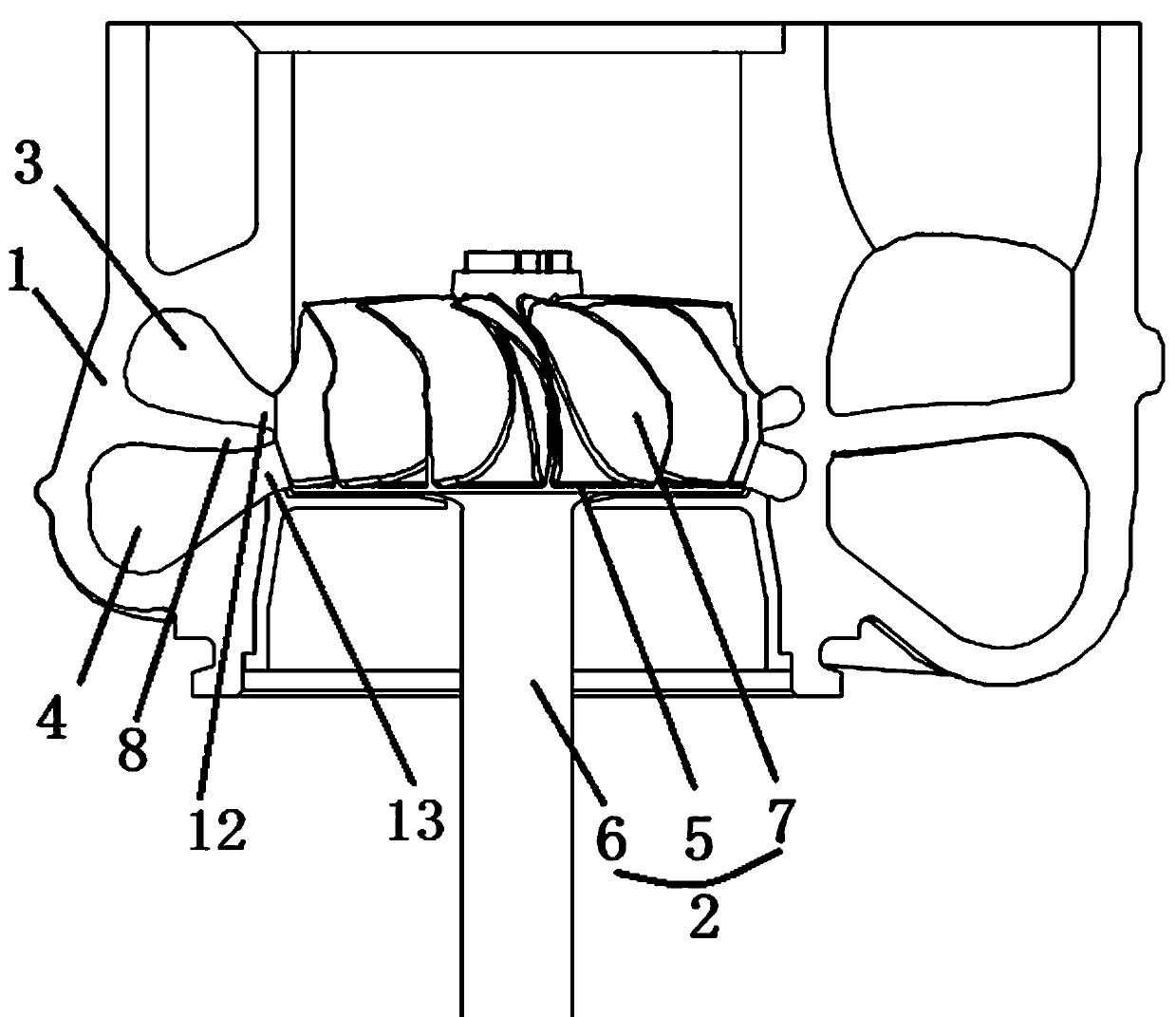
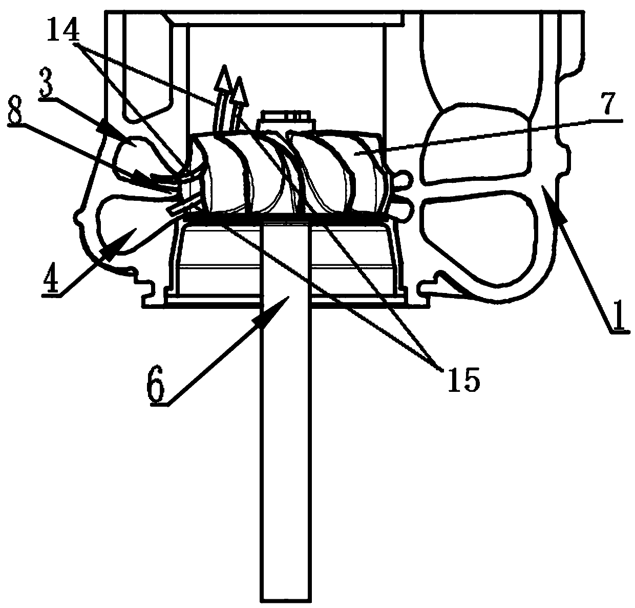
[0024] Turbine structures in the prior art such as Figure 4 , 5 As shown, the flow passage partition wall 8 between the intake passage A3 and the intake passage B4 is not in contact with the edge of the blade 7, and the gap between the flow passage partition wall 8 and the blade 7 is relatively large, resulting in the gap between the intake passage A3 and the intake passage B4. The outlet air flows are mixed together, which easily forms a turbulent fl...


PUM


Abstract

The invention discloses a dual-drive turbine, and belongs to the technical field of turbochargers. The dual-drive turbine comprises a turbine body arranged in a volute, an air inlet channel A and an air inlet channel B which are axially parallel are formed in the volute, the turbine body comprises a closed flow guiding face, a hub and a plurality of blades bent towards the same side, and the lowerends of the blades are fixed to the upper surface of the closed flow guiding face; and a flowing channel interval wall is arranged between the air inlet channel A and the air inlet channel B, a driving face A and a driving face B facing the hub are formed on the surfaces of the blades along air flows flowing out of the air inlet channel A and the air inlet channel B, the edge of the driving faceA abuts against the flowing channel interval wall, the air flow, flowing to the driving face A, of the air inlet channel A forms the air flow A, the air flow, flowing to the driving face B, of the airinlet channel B forms the air flow B, and the air flow A and the air flow B form dual-driving on the turbine. The air flow B can prevent a turbulent flow from being formed at the bottoms of the blades, and the driving force of the turbocharger and the working power of the turbine are increased.

Description

technical field [0001] The invention belongs to the technical field of turbochargers, in particular to a dual-drive turbine. Background technique [0002] With the rapid development of the automobile industry, the requirements for exhaust emissions are becoming increasingly stringent. Because the exhaust gas turbocharger can increase the intake pressure of the engine, improve the air-fuel ratio, make the engine burn more completely, save fuel, increase engine power, and reduce exhaust emissions. For the purpose of saving energy and reducing consumption, it has been more and more widely used. The turbocharger is actually an air compressor, which increases the air intake by compressing the air, uses the kinetic energy of the exhaust gas from the engine to drive the turbine, and then drives the coaxial impeller to rotate, and the impeller is pressed by the air filter pipe. The air sent to pressurize it into the cylinder. Compared with the traditional single-channel turbocharg...

Claims


Application Information

Patent Timeline
Patent Type & Authority Applications(China)
IPC IPC(8): F02B37/18F02B39/00
CPCF02B37/18F02B39/00Y02T10/12
Inventor 张运波王辰
Owner 车行天下网络科技股份有限公司
Why Eureka
Try Eureka