Calibration method and device for single-line laser radar and multi-line laser radar

A single-line laser radar and multi-line laser technology, applied in the field of data processing, can solve the problems of no solution and large calibration result error, and achieve the effect of improving the accuracy and solving the large error

Active Publication Date: 2020-05-05
盛景智能科技嘉兴有限公司
View PDF4 Cites 3 Cited by
  • Summary
  • Abstract
  • Description
  • Claims
  • Application Information

AI Technical Summary

Problems solved by technology

[0003] However, there are not many methods for extrinsic calibration of single-line lidar and multi-line lidar in the prior art. Generally, third-party sensors are needed for auxiliary calibration, which leads to large errors in calibration results.
[0004] For the above problems, no effective solution has been proposed

Method used


Image

  • Calibration method and device for single-line laser radar and multi-line laser radar
  • Calibration method and device for single-line laser radar and multi-line laser radar
  • Calibration method and device for single-line laser radar and multi-line laser radar

Examples


Embodiment 1

[0033] According to an embodiment of the present invention, an embodiment of a calibration method for a single-line laser radar and a multi-line laser radar is provided. computer system, and although a logical order is shown in the flowcharts, in some cases the steps shown or described may be performed in an order different from that shown or described herein.

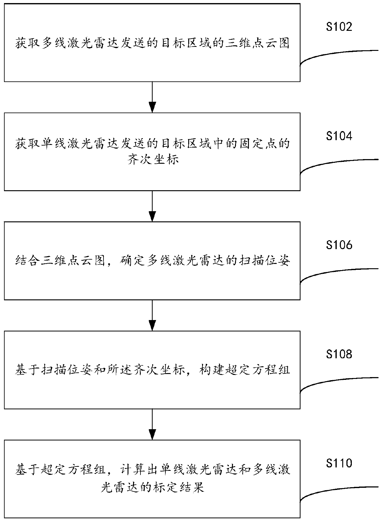
[0034] figure 1 It is a flowchart of a calibration method for a single-line laser radar and a multi-line laser radar according to an embodiment of the present invention, as shown in figure 1 As shown, the method includes the following steps:

[0035] Step S102, obtaining a three-dimensional point cloud image of the target area sent by the multi-line lidar;

[0036] Specifically, the above-mentioned three-dimensional point cloud map can be established through a multi-line lidar slam algorithm.

[0037] Step S104, acquiring homogeneous coordinates of a fixed point in the target area sent by a single-line lidar, wherei...

Embodiment 2

[0068]The present invention also provides an embodiment of a single-line laser radar and multi-line laser radar calibration device, which is used to implement the single-line laser radar and multi-line laser radar calibration method provided by the above content of the embodiment of the present invention, as follows The specific introduction of the calibration device for single-line laser radar and multi-line laser radar provided by the embodiment of the present invention.

[0069] like Figure 4 As shown, the above-mentioned calibration device for single-line lidar and multi-line lidar includes: a first acquisition unit 10 , a second acquisition unit 20 , a determination unit 30 , a construction unit 40 and a calculation unit 50 .

[0070] The first acquisition unit 10 is configured to acquire a three-dimensional point cloud image of the target area sent by the multi-line lidar;

[0071] The second acquiring unit 20 acquires the homogeneous coordinates of the fixed points in...


PUM


Abstract

The invention provides a calibration method and device for single-line laser radar and a multi-line laser radar, and relates to the technical field of data processing, and the method comprises the steps: obtaining a three-dimensional point cloud image, transmitted by the multi-line laser radar, of a target region; obtaining homogeneous coordinates of a fixed point in the target region sent by thesingle-line laser radar, the homogeneous coordinates being coordinate information obtained by scanning the fixed point by the single-line laser radar; determining the scanning pose of the multi-line laser radar in combination with a three-dimensional point cloud chart, the scanning pose being a scanning pose of the multi-line laser radar when the single-line laser radar scans the fixed point; constructing an overdetermined equation set based on the scanning pose and the homogeneous coordinates; and based on the overdetermined equation set, calculating the calibration results of the single-linelaser radar and the multi-line laser radar. The technical problem that in the prior art, errors of the calibration results of the single-line laser radar and the multi-line laser radar are large is solved.

Description

technical field [0001] The invention relates to the technical field of data processing, in particular to a calibration method and device for a single-line laser radar and a multi-line laser radar. Background technique [0002] Sensors such as cameras, lidars, and millimeter-wave radars all have their own coordinate systems, that is, the data generated by all sensors is based on the sensor's own coordinate system. However, on a carrier (for example: a three-dimensional data acquisition cart), many sensors will be installed on the car. In order to facilitate algorithm research and testing, it is necessary to convert the data obtained by each sensor into a certain inherent coordinate system, that is, the base coordinate system. , then this process is called extrinsic calibration of the sensor. [0003] However, there are not many methods for extrinsic calibration of single-line lidar and multi-line lidar in the prior art. Generally, third-party sensors are needed for auxiliary...

Claims


Application Information

Patent Timeline
Patent Type & Authority Applications(China)
IPC IPC(8): G01S7/497
CPCG01S7/497
Inventor 刘锋
Owner 盛景智能科技嘉兴有限公司
Why Eureka
Try Eureka