Synchronous permanent magnet coupler with single permanent magnet rotor

A permanent magnet rotor and coupling technology, applied in the direction of synchronous clutch/brake, permanent magnet clutch/brake, magnetic circuit rotating parts, etc., to achieve the effect of small eddy current and low temperature rise

Pending Publication Date: 2020-05-05
CCTEG SHENYANG RES INST
View PDF0 Cites 0 Cited by
  • Summary
  • Abstract
  • Description
  • Claims
  • Application Information

AI Technical Summary

Problems solved by technology

[0008] In order to solve the above problems, the present invention proposes a synchronous permanent magnet coupling with a single permanent magnet rotor, while retaining the advantages of permanent magnet coupling vibration isolation, non-contact transmission, and high efficiency, it overcomes the dual permanent magnet rotor synchronous permanent magnet coupling. T

Method used


Image

  • Synchronous permanent magnet coupler with single permanent magnet rotor
  • Synchronous permanent magnet coupler with single permanent magnet rotor
  • Synchronous permanent magnet coupler with single permanent magnet rotor

Examples


Example Embodiment

[0045] Example 1

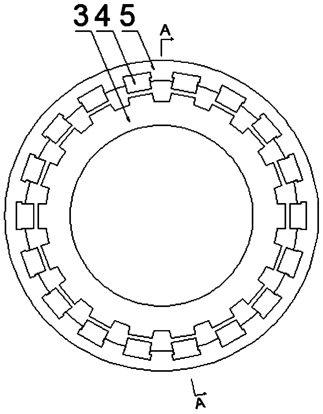
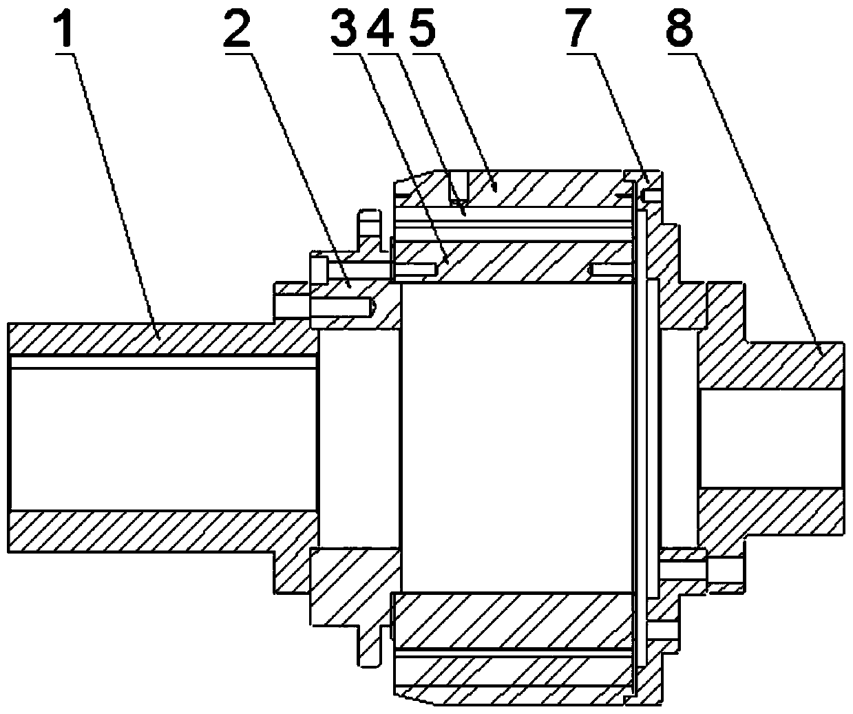
[0046] like figure 1 , figure 2 As shown, in this embodiment, the input end coupling 1 and the output end coupling 8 are used to connect the rotor of the permanent magnetic coupling with the drive system and the load, and the two can be exchanged without affecting the normal use of the equipment. The input-end adapter plate 2 and the output-end adapter plate 7 are connecting plates between the inner and outer rotors and the coupling; the reluctance inner rotor 3 has no permanent magnets 4, only a certain number of convex stages, so that the magnetic resistance of the equipment The path changes, and its number is the same as the number of salient stages on the inner rotor 3 of the reluctance. In this device, the reluctance inner rotor 3 and the permanent magnet rotor 5 can be interchanged without affecting the normal use of the device

Example Embodiment

[0047] Example 2

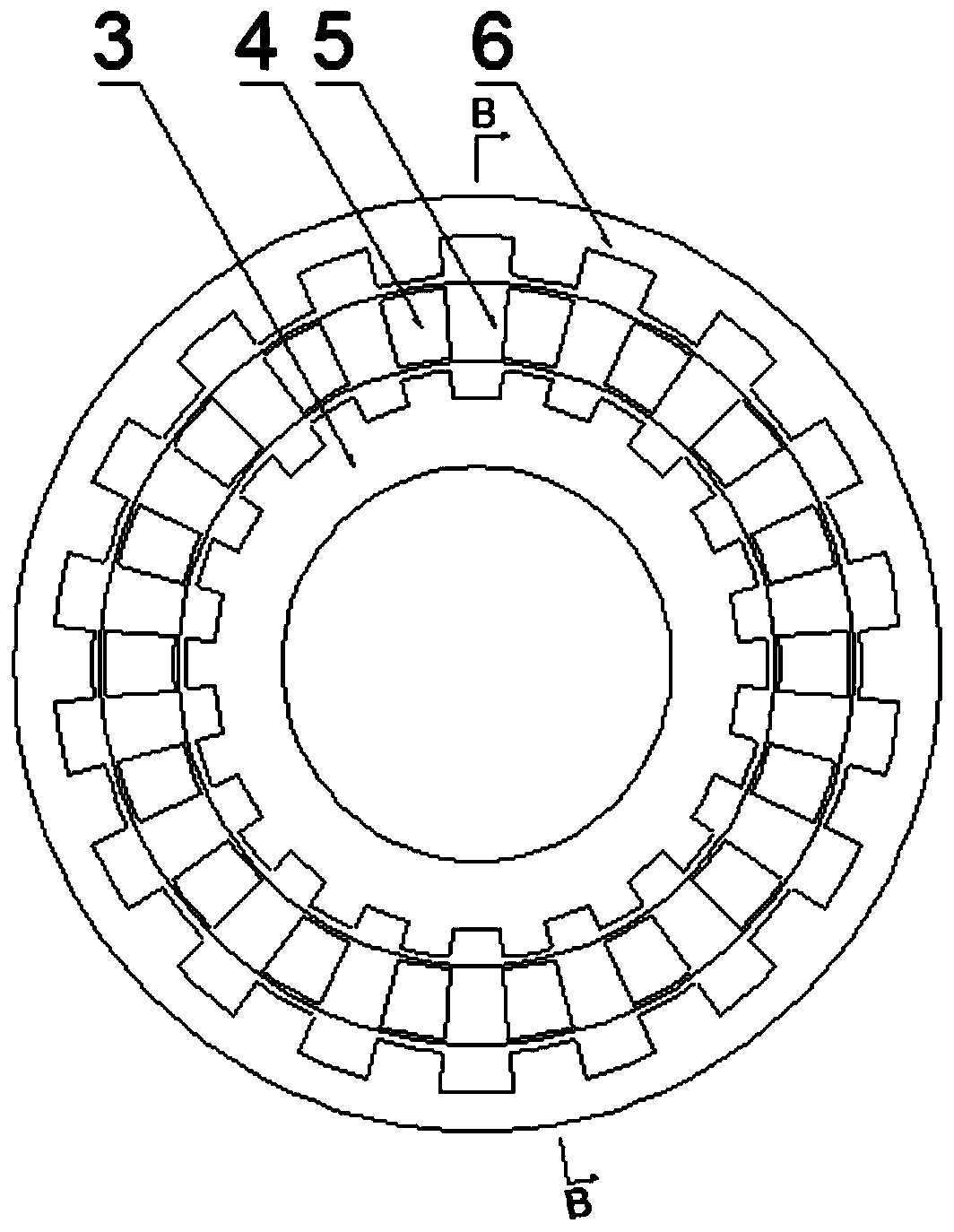
[0048] The permanent magnetic coupling in this embodiment is similar to the permanent magnetic coupling in Embodiment 1, the difference lies in the structure of the reluctance rotor. like image 3 , Figure 4 As shown, the input end coupling 1 and the output end coupling 8 are used to connect the rotor of the permanent magnetic coupling with the drive system and the load, and the two can be exchanged without affecting the normal use of the equipment. The reluctance inner rotor 3 and the reluctance outer rotor 6 are both arranged on the right end face of the input adapter plate 2, the permanent magnet rotor 5 is arranged on the left end face of the output end adapter plate 7, and the reluctance inner rotor 3 and the reluctance outer rotor No permanent magnet 4 is placed on 6, only the same number of salient stages, and the salient stages of the inner and outer rotors of the reluctance are opposite one by one, and the salient stages are axially overlapped, s...

Example Embodiment

[0049] Example 3

[0050] like Figure 5 As shown, the input end coupling 1 and the output end coupling 8 are used to connect the rotor of the permanent magnetic coupling with the drive system and the load, and the two can be exchanged without affecting the normal use of the equipment. The input side reluctance rotor 9 is a reluctance rotor and it is a disc-shaped convex structure, and the size of the convex is related to the size of the permanent magnet 4 and the transmission torque. In the permanent magnet rotor fixed plate 10, the magnet mounting plate 11 is made of non-magnetic material. The magnet mounting plate 11 is slotted on one side, and the permanent magnet 4 is placed in the groove. The magnet mounting plate 11 and the magnet cover 13 seal the permanent magnet 4 together. . The sleeve 12 is used to connect the double-disc reluctance rotors so that the two rotors can run synchronously. The permanent magnet rotor fixing disc 10 is used together with the permanent ...


PUM


Abstract

The invention belongs to transmission equipment in the coal mine industry, and provides a synchronous permanent magnet coupler with a single permanent magnet rotor. The coupler comprises an input endcoupling, an output end coupling, a permanent magnet rotor and a reluctance rotor. The permanent magnet rotor is connected with the reluctance rotor. The reluctance rotor is connected with one of theinput end coupling and the output end coupling, and the permanent magnet rotor is connected with the other one of the input end coupling and the output end coupling. The reluctance rotor is a salientpole type rotor formed by laminating silicon steel sheets. The permanent magnet rotor is provided with accommodating grooves. The number of teeth of the reluctance rotor is the same as that of the accommodating grooves and is an even number. Permanent magnets are installed in the accommodating grooves, and magnetic poles of the adjacent permanent magnets are arranged in a staggered mode. Due to the advantages of the permanent magnet coupler, the problem of demagnetization caused by overhigh temperature rise of the magnetic steel due to load jamming of a double-permanent-magnet-rotor synchronous permanent magnet coupler is solved. The structure of the permanent magnet coupler is simplified. The requirement of the permanent magnet coupler for the magnetic steel is reduced, and the productioncost of the permanent magnet coupler is reduced.

Description

technical field [0001] The invention belongs to transmission connection equipment, in particular to permanent magnet coupler equipment. Background technique [0002] The transmission equipment is responsible for transferring the output energy of the motor and other power equipment to the working machine, and its efficiency directly affects the production cost. At present, most of the transmission equipment in our country are hydraulic couplings and eddy current permanent magnet couplings. Both of these two transmission equipment need to rely on the existence of slip speed to realize energy transmission, which will cause loss of efficiency and cause transmission The temperature of the components rises, and when overloaded, the temperature of the transmission components will further rise, affecting the normal operation of the equipment, and there are hidden dangers. [0003] The synchronous permanent magnet coupler is equipped with magnetic steel on the inner and outer rotors...

Claims


Application Information

Patent Timeline
IPC IPC(8): H02K49/06H02K49/10H02K1/24H02K1/27
CPCH02K1/246H02K1/274H02K49/06H02K49/106
Inventor 王雷刘昊李健朱玉芹刘佳张黎
Owner CCTEG SHENYANG RES INST
Why Eureka
Try Eureka