
Anti-reverse circuit of bridge drive circuit

A bridge drive circuit, power drive circuit technology, applied in failsafe circuits, logic circuit interface devices, logic circuit connection/interface layout, etc., can solve problems such as damage, diode heat generation, overcurrent damage, etc., to prevent power Reverse connection, stable conduction state, and solve the effect of large heat generation

Pending Publication Date: 2020-05-05
JING JIN ELECTRIC TECH CO LTD
View PDF6 Cites 0 Cited by
  • Summary
  • Abstract
  • Description
  • Claims
  • Application Information

AI Technical Summary

Problems solved by technology

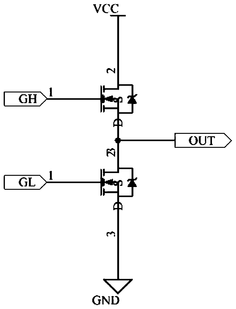
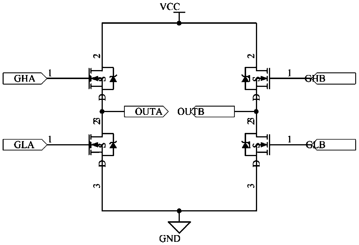
In the high-current bridge drive circuit, the switch tube of the bridge arm mostly uses N-MOSFET or IGBT. Since there are body diodes in N-MOSFET and IGBT, if the power supply is reversed, the body diode will be directly turned on, resulting in over-current damage.
However, the anti-reverse method of general circuits mostly uses power diodes. If the current of the bridge drive circuit is particularly large, it will cause excessive heat generation of the diodes, which will cause damage

Method used


Image

  • Anti-reverse circuit of bridge drive circuit
  • Anti-reverse circuit of bridge drive circuit
  • Anti-reverse circuit of bridge drive circuit

Examples


Embodiment Construction

[0021] Exemplary embodiments of the present application will be described in more detail below with reference to the accompanying drawings. Although exemplary embodiments of the present application are shown in the drawings, it should be understood that the present application may be embodied in various forms and should not be limited to the embodiments set forth herein. Rather, these embodiments are provided so that the present application can be more thoroughly understood, and the scope of the present application can be fully conveyed to those skilled in the art.

[0022] The invention discloses an anti-reverse circuit of a bridge drive circuit.

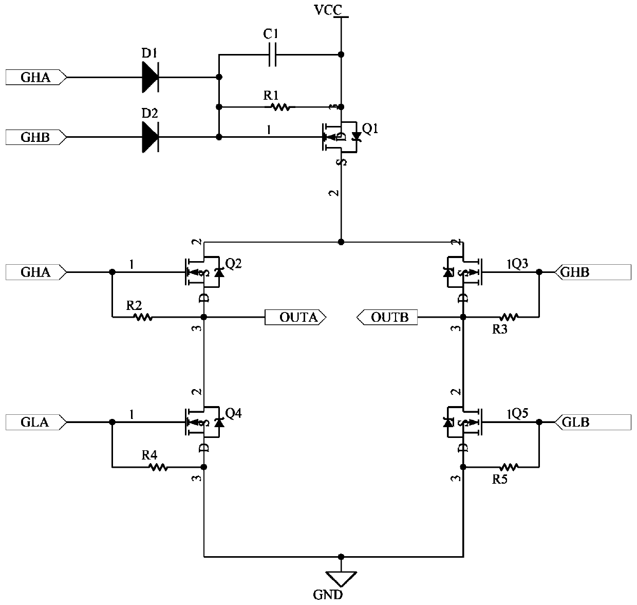
[0023] see figure 1 , the anti-reverse circuit in the embodiment of the present invention includes a bridge drive circuit and an anti-reverse circuit, and the anti-reverse circuit includes a first resistor R 1 , the first capacitance C 1 and the first MOS tube Q 1 ;

[0024] Among them, the first MOS tube Q 1 The source is co...


PUM


Abstract

The invention discloses an anti-reverse circuit of a bridge drive circuit. The anti-reverse circuit comprises a bridge drive circuit and an anti-reverse circuit. The anti-reverse circuit comprises a first resistor, a first capacitor and a first MOS transistor. A source electrode of the first MOS tube is connected with a voltage source, a drain electrode of the first MOS tube is connected with thebridge drive circuit, the first resistor and the first capacitor are connected in parallel to form an RC parallel circuit, one end of the RC parallel circuit is connected with the voltage source, andthe other end of the RC parallel circuit is connected with a grid electrode of the first MOS tube. According to the invention, the problem of large heat productivity of the diode anti-reverse circuitis solved, and the anti-reverse connection of the circuit is effectively ensured.

Description

technical field [0001] The present application relates to the field of circuit design, in particular to an anti-reverse circuit of a bridge drive circuit. Background technique [0002] The bridge drive circuit includes a half-bridge drive circuit, an H-bridge drive circuit, a three-phase full-bridge drive circuit and multiple full-bridge drive circuits. Bridge drive circuits have a common feature, they all need at least one upper bridge arm and lower bridge arm. In the high-current bridge drive circuit, the switch tube of the bridge arm mostly uses N-MOSFET or IGBT. Since there are body diodes in N-MOSFET and IGBT, if the power supply is reversed, the body diode will be directly turned on, resulting in overcurrent damage. However, the anti-reverse method of general circuits mostly uses power diodes. If the current of the bridge drive circuit is particularly large, it will cause excessive heat generation of the diodes, which will cause damage. Contents of the invention ...

Claims


Application Information

Patent Timeline
Patent Type & Authority Applications(China)
IPC IPC(8): H03K19/0175H03K19/007
CPCH03K19/017509H03K19/007
Inventor 李永亮张涛张浩加布里埃尔·加列戈斯·洛佩兹
Owner JING JIN ELECTRIC TECH CO LTD
Learn More