Device for laser interstitial thermotherapy system
A laser and hyperthermia technology, used in phototherapy, parts of surgical instruments, medical science, etc., can solve the problems of cumbersome processing of colloids, thermal expansion and denaturation, and bursting.
- Summary
- Abstract
- Description
- Claims
- Application Information
AI Technical Summary
Problems solved by technology
Method used
Image
Examples
Embodiment 1
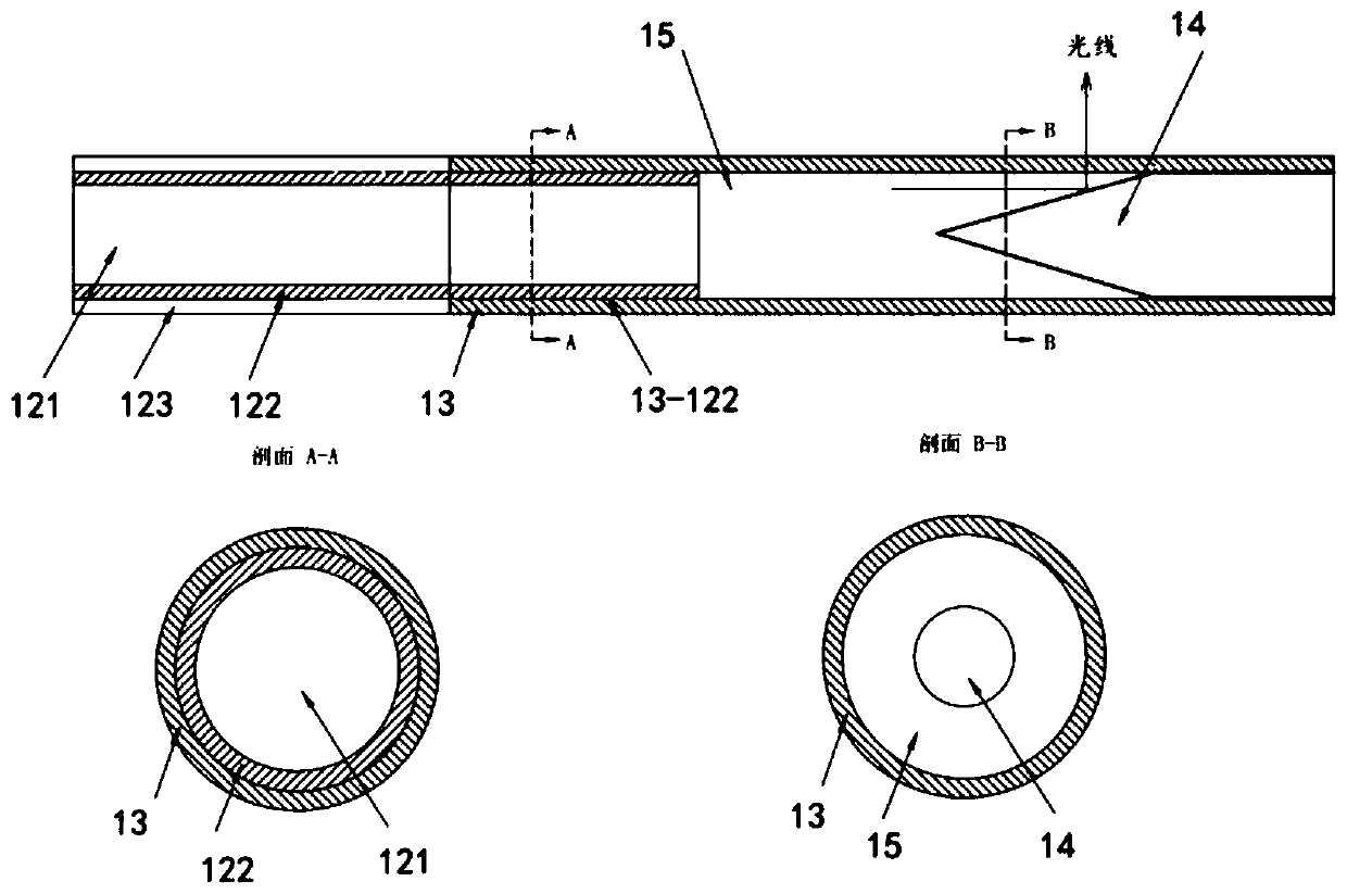
[0050] refer to figure 1 , shows a schematic diagram of a device for a laser interstitial hyperthermia system according to an embodiment of the present invention, a device 10 for a laser interstitial hyperthermia system includes a connector 11, an optical fiber 12, a sleeve 13, and a light steering Section 14. The shape and structure of the connector 11 is only schematic, and any structure or model that can complete the connection with the laser generator or other connectors is acceptable. The length of the optical fiber 12 can be adjusted as required, and the optical fiber can be any suitable type of optical fiber, as long as it can be sealed with the sleeve 13. Preferably, the optical fiber is a silica glass optical fiber, and the connection can be realized by discharge fusion. The sleeve 13 is made of a suitable light-transmitting material, and is sealed and connected with the optical fiber and the light turning part 14. Preferably, the connection can be realized by discha...
Embodiment 2
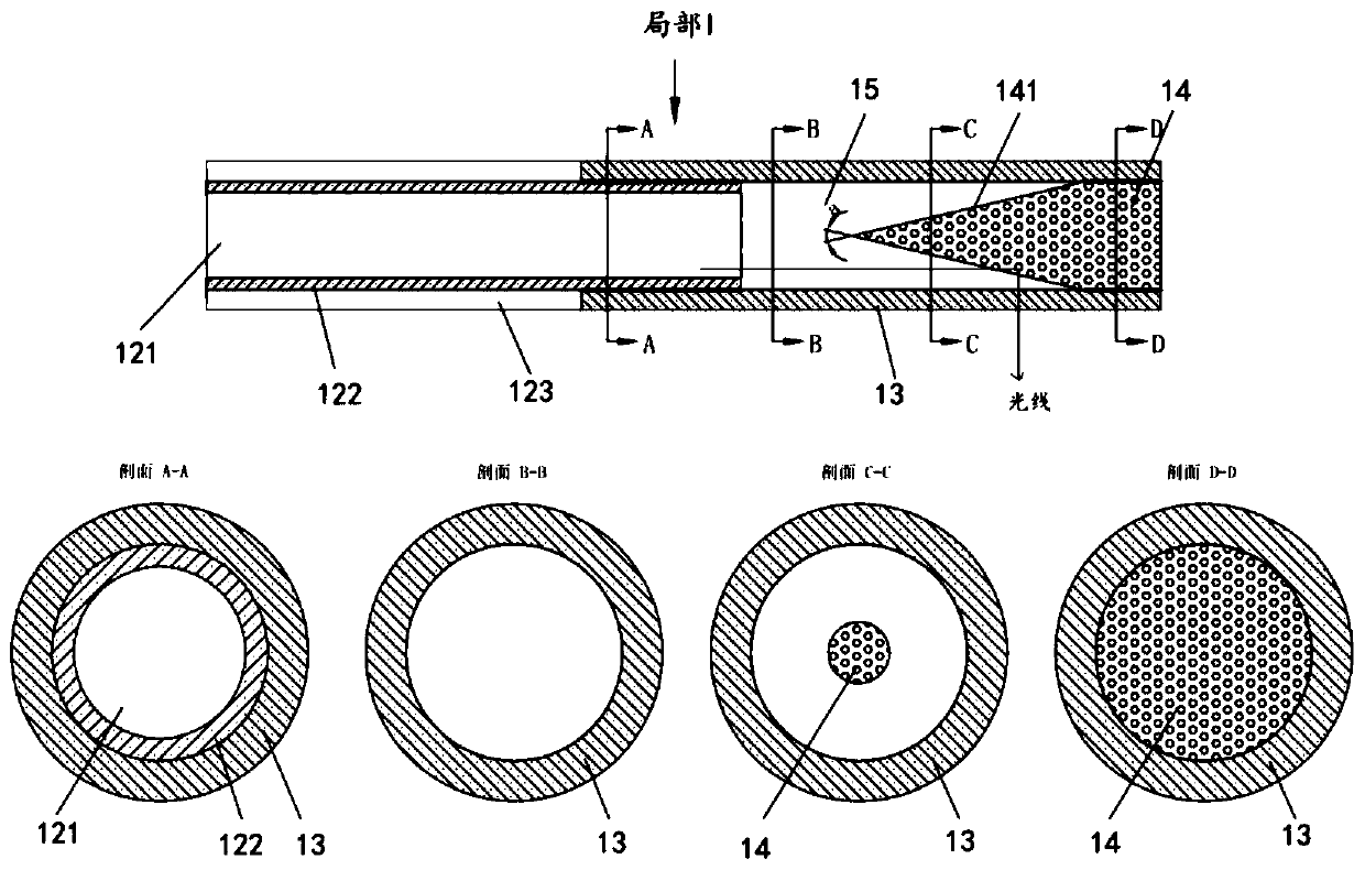
[0055] image 3 is a cross-sectional view along the axial direction of another specific example of Part I, wherein the light redirecting portion 14 includes scattering particles, and the scattering particles may be metal particles, oxide particles, air bubbles, and the like. The optical fiber includes a core 121 , a cladding 122 and a protective layer 123 . The sleeve 13 is connected to the cladding 122, and the connection interface is shown by thick lines, and the light redirecting part 14 is connected to the sleeve 13, and the connection interface is shown by thick lines. Four cross-sections A-A, B-B, C-C and D-D are shown at the same time, and those skilled in the art can understand that, for convenience of description, they are not shown in scale. The angle of the cone portion of the light turning portion 14 is a, and the angle a can be selected according to needs, and the preferred range is 15° to 150°, such as 30°, 45°, 60°, so that the cone portion can have different l...
Embodiment 3
[0060] refer to Figure 4 , Figure 4 It is a sectional view of part I along the axial direction of another specific example, showing the core 121 , the cladding 122 and the protective layer 123 of the optical fiber. The sleeve 13 is connected to the cladding 122, and the connected interface is shown by a thickened line, and the light turning part 14 is connected to the sleeve 13, and the connected interface is shown by a thickened line; image 3 The difference is that the angle b of the cone portion of the light turning portion 14 is different from the angle a in Embodiment 2, and the surface of the cone portion is a diffuse reflection surface, and the change of the light emission direction can pass through the diffuse reflection surface of the cone portion It is realized by cooperating with the scattering particles contained in the light redirecting part.
PUM
| Property | Measurement | Unit |
|---|---|---|
| melting point | aaaaa | aaaaa |
Abstract
Description
Claims
Application Information
 - R&D
- Intellectual Property
- Life Sciences
- Materials
- Tech Scout
- Unparalleled Data Quality
- Higher Quality Content
- 60% Fewer Hallucinations
Browse by: Latest US Patents, China's latest patents, Technical Efficacy Thesaurus, Application Domain, Technology Topic, Popular Technical Reports.
© 2025 PatSnap. All rights reserved.Legal|Privacy policy|Modern Slavery Act Transparency Statement|Sitemap|About US| Contact US: help@patsnap.com


