Wire cutting device for antenna

A wire and tangent technology, applied in the field of antenna manufacturing, can solve problems such as cumbersome operation, low production efficiency, and long production time of a single wire, and achieve the effects of easy cleaning, improved efficiency, and convenient operation

Active Publication Date: 2022-02-18
东莞市天技实业有限公司
View PDF9 Cites 0 Cited by
  • Summary
  • Abstract
  • Description
  • Claims
  • Application Information

AI Technical Summary

Problems solved by technology

[0006] When using this wire cutting device for production to cut the wire, four cuts are required. After each cut, the height of the cam needs to be adjusted, and then cut again until the wire is cut. The operation is cumbersome and the production of a single wire takes a long time. , low production efficiency

Method used


Image

  • Wire cutting device for antenna
  • Wire cutting device for antenna
  • Wire cutting device for antenna

Examples


Embodiment Construction

[0042] The present invention will be described in further detail below in conjunction with the accompanying drawings.

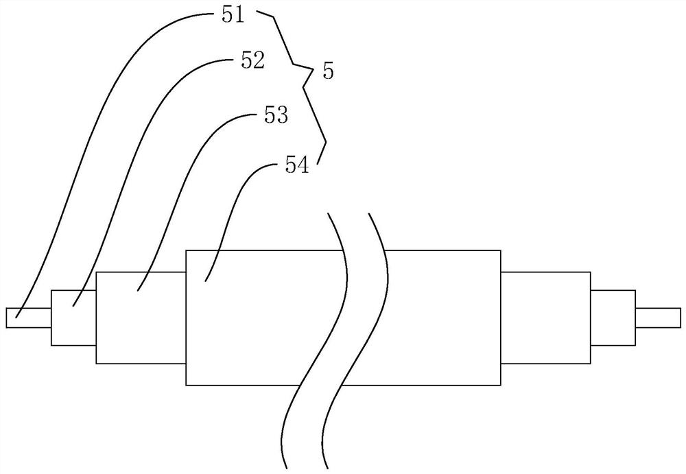
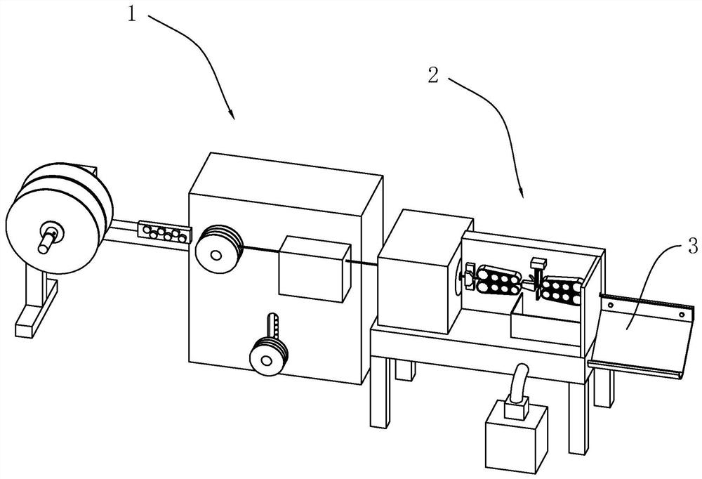
[0043] refer to figure 2 , is a wire cutting device for antennas disclosed in the present invention, including a feeding assembly 1 for feeding, a wire cutting assembly 2 for cutting wires 5 and a receiving assembly 3 for collecting and cutting wires 5 .

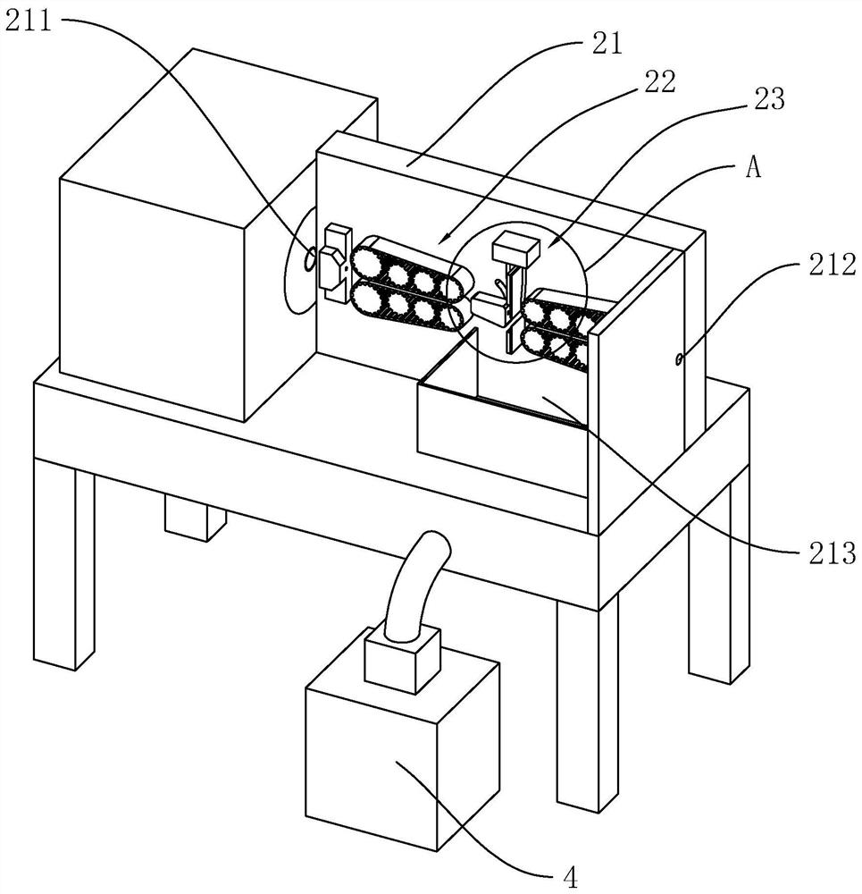
[0044] refer to image 3 , The thread cutting assembly 2 includes a box body 21 , a transmission mechanism and a cutting mechanism 23 ; wherein, the box body 21 is provided with a wire inlet 211 and a wire outlet 212 , and the transmission mechanism is used to transmit the wire 5 .

[0045] refer to Figure 4 as well as Figure 5 , the thread cutting mechanism includes a fixed cutter 231 and a moving cutter 232, the upper end of the side wall of the movable cutter 232 is connected with a connecting plate 233, the connecting plate 233 is fixedly connected with a connecting rod 234, the connecting rod 234...


PUM


Abstract

The invention relates to the technical field of antenna manufacturing, in particular to a wire cutting device for antennas, which includes a feeding assembly for feeding, a wire cutting assembly for cutting the wires, and a receiving assembly for collecting and cutting the wires; the wire cutting assembly includes Box body, transmission mechanism and cutting mechanism; there are wire inlets and outlets on the box body, and the transmission mechanism is used to transmit wires; the thread cutting mechanism includes a fixed knife and a moving knife, and the upper end of the side wall of the moving knife is connected with a connecting plate, and the connecting plate is fixed. A connecting rod is connected, and the connecting rod is slidingly connected with the box body. The end of the connecting plate away from the moving tool is connected with a sliding block. The upper end of the sliding block is provided with a cam, and four protrusions are arranged at intervals on the circumference of the cam. The four protrusions The maximum distance between the top and the outer circular surface of the cam becomes larger successively, and an elastic restoring part is arranged under the sliding block. The invention has the effects of convenient operation, shorter time for producing a single wire, and improved production efficiency.

Description

technical field [0001] The invention relates to the technical field of antenna manufacturing, in particular to a wire cutting device for antennas. Background technique [0002] Antenna is a converter that transforms the guided wave propagating on the transmission line into electromagnetic waves propagating in the unbounded medium, or vice versa. It is a component used in radio equipment to transmit or receive electromagnetic waves. [0003] Such as figure 1 As shown, in order to make the wire of the antenna, the wire 5 includes a conductive wire 51, a first insulating layer 52, a shielding layer 53 and a second insulating layer 54 arranged in sequence from the inside to the outside, and the two ends of the shown conductive wire 51 extend out of the described Two ends 52 of the first insulating layer, the two ends of the first insulating layer 52 extend from the two ends of the shielding layer 53 , the two ends of the shielding layer 53 extend from the two ends of the second...

Claims


Application Information

Patent Timeline
Patent Type & Authority Patents(China)
IPC IPC(8): B21F11/00B21F23/00B08B5/02B08B15/04
CPCB21F11/00B21F23/00B08B5/02B08B15/04
Inventor 敬邦敏雷传林
Owner 东莞市天技实业有限公司
Why Eureka
Try Eureka