
Metal cutting machine tool capable of quickly clamping

A technology of metal cutting and clamping mechanism, which is applied to the accessories of toolholders, metal processing equipment, turning equipment, etc., which can solve the problems of easily affecting the cutting of workpieces, insufficient technology, and slow clamping speed, so as to reduce defective cutting products High efficiency, fast clamping speed and stable clamping effect

Inactive Publication Date: 2020-05-08
柳州市万仓机械制造有限公司
View PDF13 Cites 6 Cited by
  • Summary
  • Abstract
  • Description
  • Claims
  • Application Information

AI Technical Summary

Problems solved by technology

[0003] Due to the imperfect technology of the existing metal cutting machine tool fixtures, the machine tool fixtures only clamp the bottom outer wall of the workpiece, the clamping degree is not enough and the clamping speed is slow, and due to the high cutting force, vibration will occur, and the vibration is large, which will cause The workpiece is loose, which easily affects the cutting of the workpiece, resulting in cutting errors, resulting in defective products

Method used


Image

  • Metal cutting machine tool capable of quickly clamping
  • Metal cutting machine tool capable of quickly clamping
  • Metal cutting machine tool capable of quickly clamping

Examples


Embodiment 1

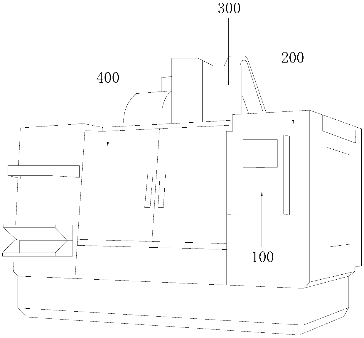
[0036] see Figure 1-7 , the present invention provides a technical solution for a fast clamping metal cutting machine tool: its structure includes a controller 100, a metal cutting machine tool body 200, a metal cutting device 300, a protective door 400, and a quick chuck 500 for cutting parts. The machine tool body 200 is equipped with a controller 100, the controller 100 is electrically connected to the metal cutting device 300, and the cutting part quick chuck 500 is provided directly below the metal cutting device 300, and the cutting part quick chuck 500 is built in Metal cutting machine tool body 200, the metal cutting machine tool body 200 is hinged with a protective door 400;

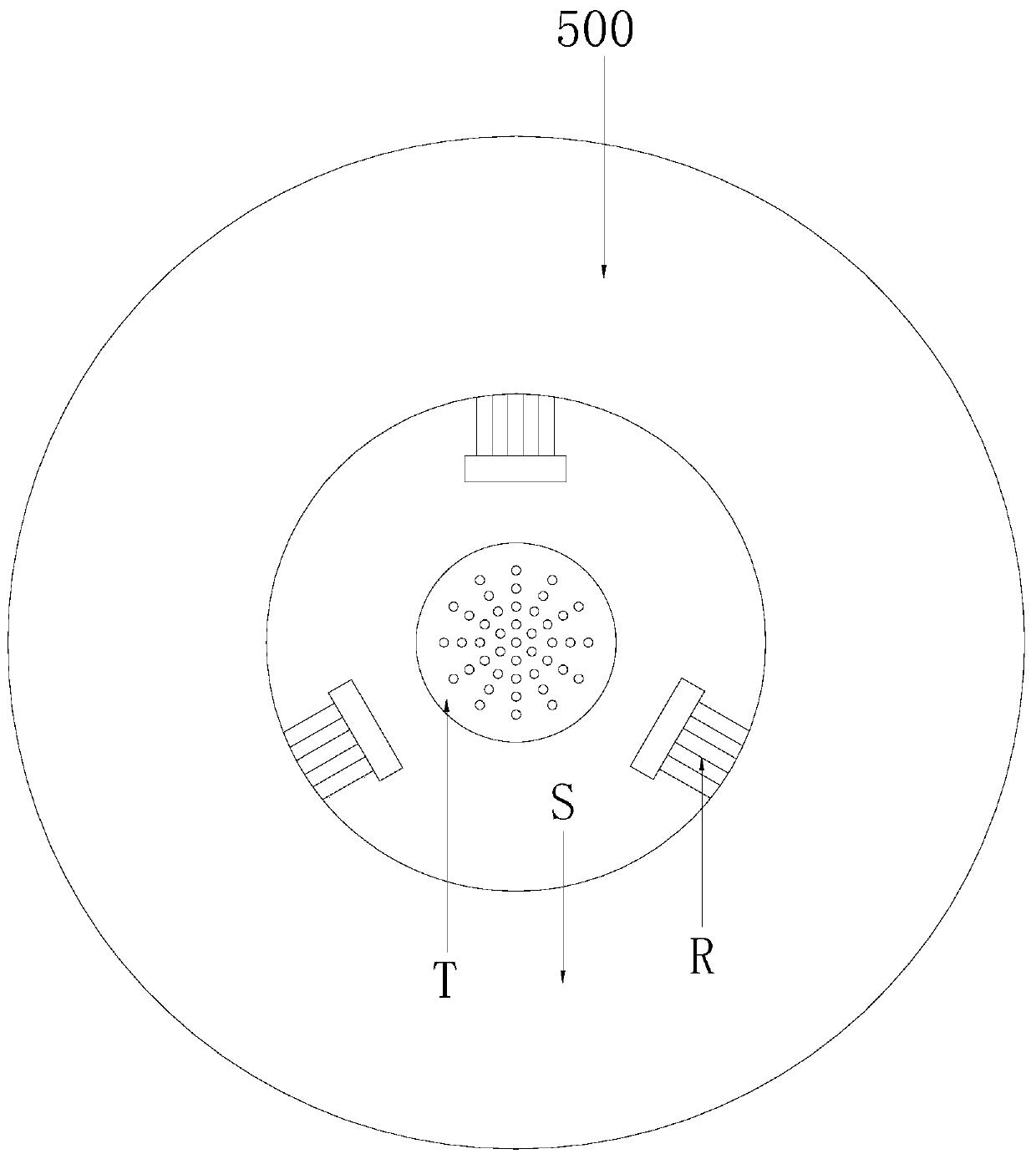
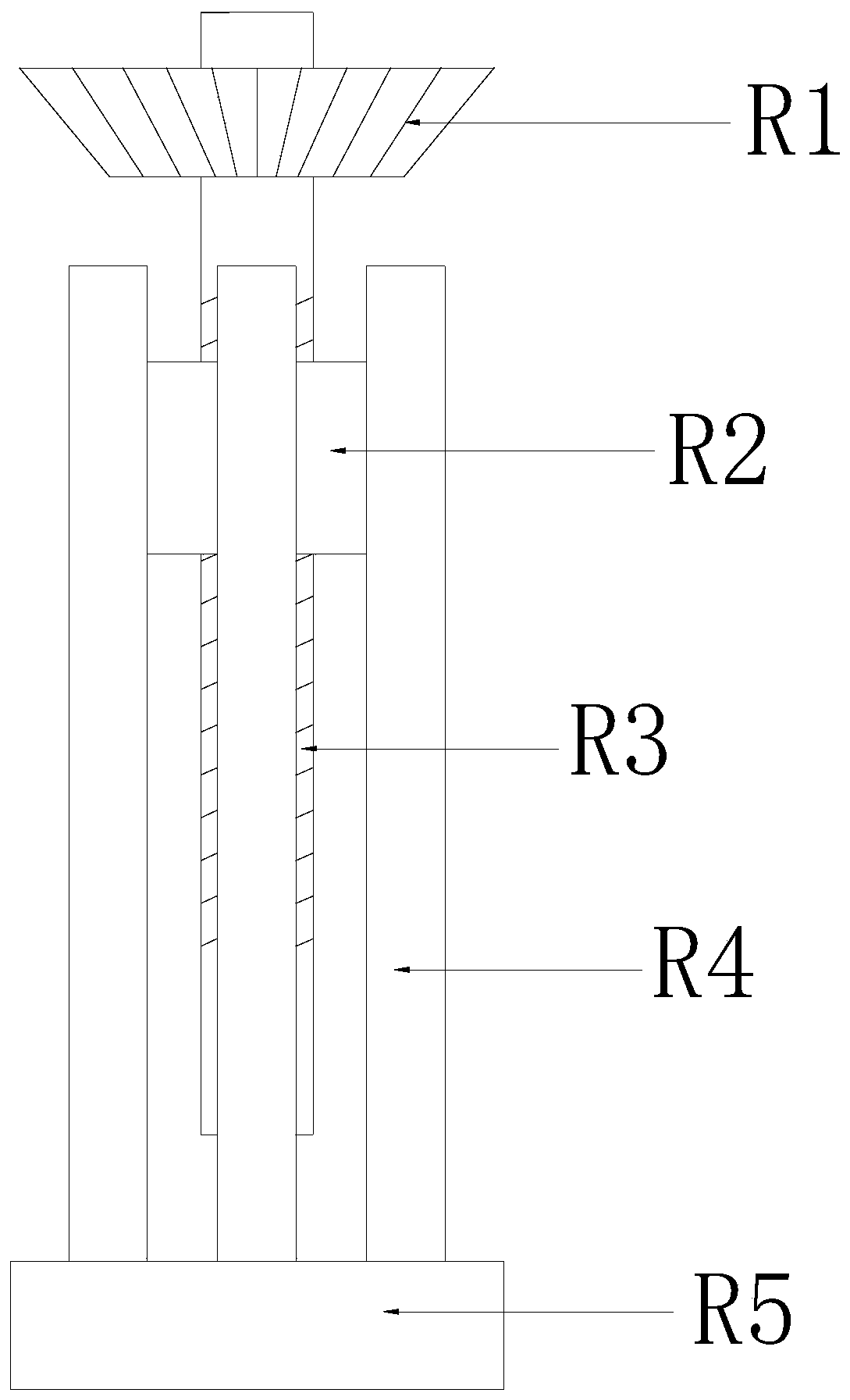
[0037] The cutting quick chuck 500 includes a main clamping mechanism R, a chuck S, and an auxiliary clamping mechanism T. The main clamping mechanism R is arranged on three equal parts of the chuck S, and the chuck S is also provided with an auxiliary clamping mechanism T, the main clamping m...

Embodiment 2

[0045] see Figure 1-9 , the present invention provides a technical solution for a fast clamping metal cutting machine tool: its structure includes a controller 100, a metal cutting machine tool body 200, a metal cutting device 300, a protective door 400, and a quick chuck 500 for cutting parts. The machine tool body 200 is equipped with a controller 100, the controller 100 is electrically connected to the metal cutting device 300, and the cutting part quick chuck 500 is provided directly below the metal cutting device 300, and the cutting part quick chuck 500 is built in Metal cutting machine tool body 200, the metal cutting machine tool body 200 is hinged with a protective door 400;

[0046] The cutting quick chuck 500 includes a main clamping mechanism R, a chuck S, and an auxiliary clamping mechanism T. The main clamping mechanism R is arranged on three equal parts of the chuck S, and the chuck S is also provided with an auxiliary clamping mechanism T, the main clamping m...


PUM


Abstract

The invention discloses a metal cutting machine tool capable of quickly clamping. The metal cutting machine tool capable of quickly clamping structurally comprises a controller, a metal cutting machine tool body, a metal cutting device, a protective door and a cutting piece quick chuck plate, the controller is arranged outside the metal cutting machine tool body, and the controller is electricallyconnected with the metal cutting device. The metal cutting machine tool capable of quickly clamping has the beneficial effects that the cutting piece quick chuck plate is arranged to have a novel structure, transversely clamping a vertical metal piece to be cut by a main clamping mechanism is carried out through the combined arrangement of the main clamping mechanism, the chuck plate and an auxiliary clamping mechanism, the auxiliary clamping mechanism is arranged to perform longitudinally adsorption and fixation on the metal piece to be cut, not only the clamping speed is high, clamping is more stable, the to-be-cut part is not affected by cutting force and vibration force, loosening, which is generated, of the to-be-cut part is avoided, the cutting quality is improved, and the cutting defective rate is reduced.

Description

technical field [0001] The invention relates to the technical field of metal cutting machine tools, in particular to a fast clamping metal cutting machine tool. Background technique [0002] Metal cutting is a method of material removal and forming in the metal forming process. It still occupies a large proportion in today's mechanical manufacturing. The metal cutting process is a process of interaction between the workpiece and the tool. The tool removes excess metal from the workpiece to be processed. And under the premise of controlling productivity and cost, the workpiece can obtain the geometric accuracy, dimensional accuracy and surface quality that meet the design and process requirements. In order to realize this process, there must be relative motion between the workpiece and the tool, that is, cutting motion. Provided by metal cutting machine tools, machine tools, fixtures, tools and workpieces constitute a machining process system, and fixtures are particularly im...

Claims


Application Information

Patent Timeline
Patent Type & Authority Applications(China)
IPC IPC(8): B23B31/169B23B31/10
CPCB23B31/10B23B31/16
Inventor 王康康
Owner 柳州市万仓机械制造有限公司
Learn More