Automatic visual laser marking system

A laser marking and visual technology, applied in the field of laser marking, can solve the problems of high price, high manufacturing cost and insufficient intelligence, and achieve the effect of improving work efficiency and processing efficiency

Active Publication Date: 2020-05-08
浙江一诺机电有限公司
View PDF4 Cites 3 Cited by
  • Summary
  • Abstract
  • Description
  • Claims
  • Application Information

AI Technical Summary

Problems solved by technology

In the marking process, the position of the workpiece flowing on the assembly line is often consistent with that of the template workpiece. In actual production, it is necessary to use expensive fixtures to position the workpiece, so the manufacturing cost is high and not intelligent enough.

Method used


Image

  • Automatic visual laser marking system
  • Automatic visual laser marking system
  • Automatic visual laser marking system

Examples


Embodiment 1

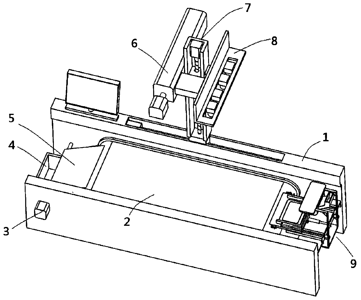
[0045] see Figure 1-4 , an automatic visual laser marking system, including a conveyor belt assembly and a laser marking assembly, one end of the conveyor belt mechanism 2 contained in the conveyor belt assembly is provided with an automatic feeding mechanism 9, and the other end of the conveyor belt mechanism 2 is provided with a receiving mechanism , the laser marking component is arranged on the top side of the conveyor belt component, and is used to automatically identify and mark the workpieces conveyed by the conveyor belt component.

[0046] The automatic feeding mechanism 9 is used to place the workpiece and push the workpiece to the upstream position of the conveyor belt mechanism 2. The workpiece is transferred to the designated position by the conveyor belt mechanism 2 and marked by the laser marking machine 6. The receiving mechanism Used to receive marked workpieces.

[0047] The conveyor belt assembly includes a frame 1 and a conveyor belt mechanism 2. The lase...

Embodiment 2

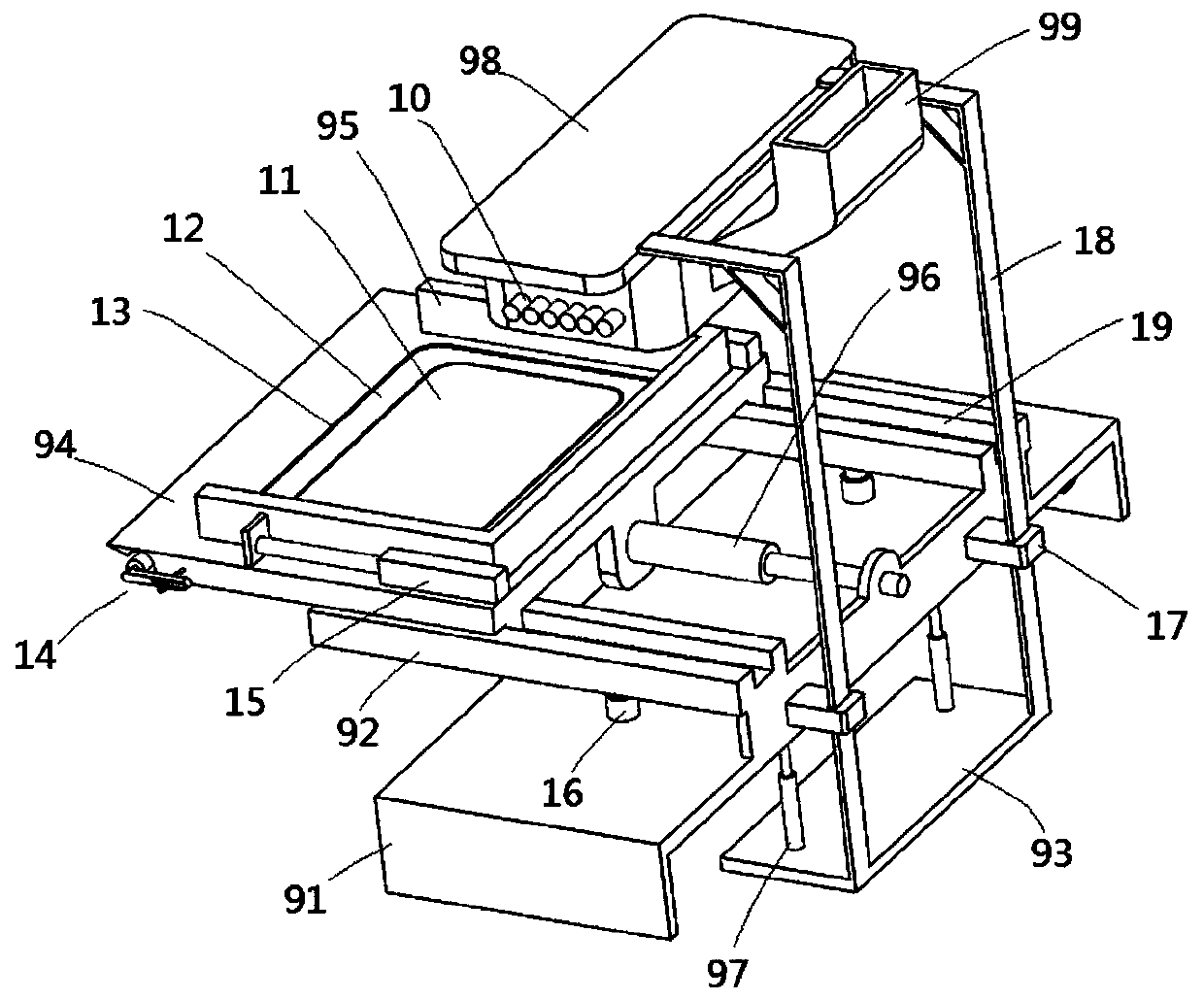
[0062] see Figure 5 , as a further improvement of the present invention, one side end surface of the sliding feeding plate 94 close to the conveyor belt mechanism 2 is in contact with the outer surface of the conveyor belt in the conveyor belt mechanism 2, and the top surface of the sliding feeding plate 94 is in contact with the conveyor belt mechanism 2 The top surface of the inner conveyor belt is on the same plane, and the end surface of the sliding feeding plate 94 close to the conveyor belt mechanism 2 is an arc-shaped surface, and the arc-shaped surface is provided with a groove 26 along its length direction, and the groove 26 is provided with Protection mechanism 14 for conveyor belt rolling contact.

[0063] Wherein, the protection mechanism 14 includes a rolling column 1401 and a side plate 1402, the rolling column 1401 is movably arranged in the groove 26, the two ends of the rolling column 1401 are connected with the side plate 1402 through a pin shaft, the end of...

Embodiment 3

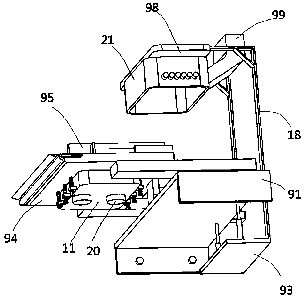
[0067] see Figure 6 , Figure 7 In this embodiment, as a further improvement based on Embodiment 2, in the present invention, a mechanism for assisting in moving the workpiece can be provided in the protective cover 21 to prevent the workpiece from being completely evenly distributed on the vibrating plate 11 under vibration.

[0068]An annular mounting frame 43 is movable in the protective cover 21, and an installation cavity 38 is provided in the protective cover 21 housing, and a movable block 31 is arranged in each installation cavity 38, and threaded holes are arranged in the movable block 31. Screw mandrel 32 is provided with along protective cover 21 depth direction in installation chamber 38, and screw mandrel 32 is threadedly engaged with movable block 31, and drive motor 30 that drives screw mandrel 32 rotations is installed on top plate 98, and installation chamber 38 and protective cover 21 pass through The through hole 35 communicates, and the mounting frame 43 ...


PUM

PropertyMeasurementUnit
thicknessaaaaaaaaaa

Abstract

The invention discloses an automatic visual laser marking system. The automatic visual laser marking system comprises a conveying belt assembly and a laser marking assembly, wherein an automatic feeding mechanism is arranged at one end of a conveying belt mechanism contained in the conveying belt assembly, a receiving mechanism is arranged at the other end of the conveying belt mechanism, the laser marking assembly is arranged on one side of the top of the conveying belt assembly and used for automatically identifying and marking workpieces conveyed through the conveying belt assembly, the automatic feeding mechanism is used for placing the workpieces and pushing the workpieces to the upstream position of the conveying belt mechanism, the workpieces are conveyed to a designated position through the conveying belt mechanism to be marked through a laser marking machine, the material receiving mechanism is used for receiving the marked workpieces, the conveying belt assembly comprises a machine frame and the conveying belt mechanism, and the laser marking assembly comprises the laser marking machine, a vertical frame, a CCD camera device and a controller. The automatic visual laser marking system is simple in structure, facilitates automatic marking and improves the working efficiency.

Description

technical field [0001] The invention relates to the field of laser marking, in particular to an automatic visual laser marking system. Background technique [0002] At present, laser marking machines are mainly used for marking objects on the assembly line. In the marking process, the position of the workpiece flowing on the assembly line is often consistent with that of the template workpiece. In actual production, it is necessary to use expensive fixtures to position the workpiece, so the manufacturing cost is high and not intelligent enough. [0003] The existing marking machine has a visual detection device, which obtains the position information of the workpiece after the visual detection, and the controller controls the marking machine to mark the workpieces one by one. Turn it on to work. In this mode of operation, the workpiece must be placed in the correct position before marking the workpiece. If the workpiece is randomly scattered on the conveyor belt, it will no...

Claims


Application Information

Patent Timeline
Patent Type & Authority Applications(China)
IPC IPC(8): B23K26/362B23K26/70
CPCB23K26/362B23K26/702
Inventor 马浩臣
Owner 浙江一诺机电有限公司
Why Eureka
Try Eureka