Steel pipe welding device

A technology for welding devices and steel pipes, applied in auxiliary devices, welding equipment, welding equipment, etc., can solve the problems of high stability requirements for welding guns, high physical exertion of operators, uneven welding quality, etc., and improve the level of And stability, improve welding efficiency, good quality effect

Inactive Publication Date: 2020-05-08
谭宁
View PDF0 Cites 2 Cited by
  • Summary
  • Abstract
  • Description
  • Claims
  • Application Information

AI Technical Summary

Problems solved by technology

[0002] In the traditional steel pipe welding process, the operator needs to hold the welding gun to weld along the circumferential welding seam of the steel pipe, which puts forward higher requirements for the experience of the welder. Due to the poor stability of holding with both hands, it consumes a lot of physical strength. Moreover, the circular welding seam has high requirements on the stability of the welding gun, which makes the welding efficiency of steel pipes low, and consumes a lot of physical strength for the operators. At the same time, the welding quality is uneven.

Method used


Image

  • Steel pipe welding device
  • Steel pipe welding device
  • Steel pipe welding device

Examples


Embodiment 1

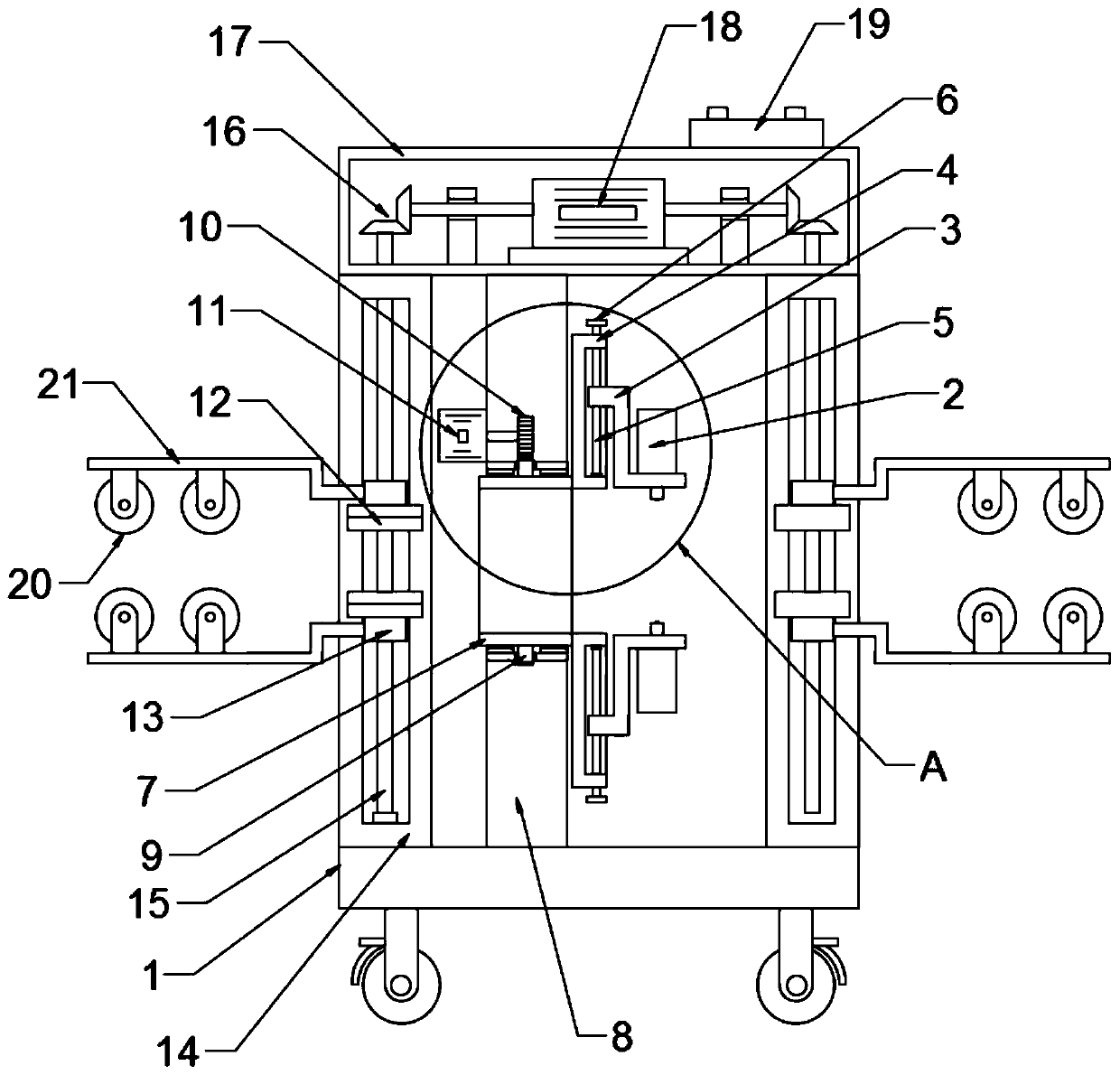
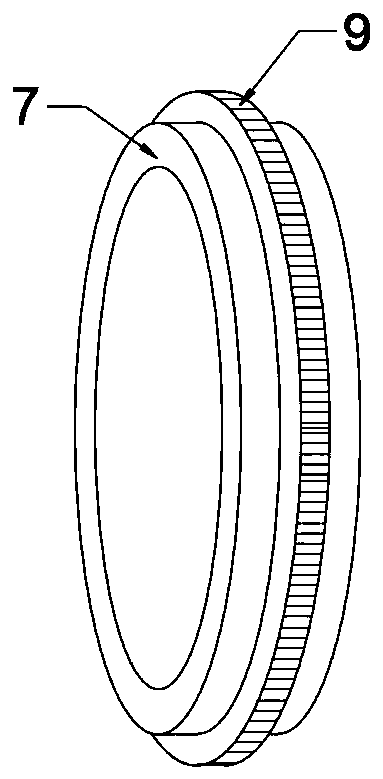
[0020] see Figure 1-4 , in an embodiment of the present invention, a steel pipe welding device includes a housing 1, a welding mechanism and a clamping mechanism; the housing 1 is a hollow box structure with openings on both sides, and a rotating drum is arranged inside the housing 1 7. The drum 7 is a hollow cylinder with openings at both ends. A welding mechanism is provided on the drum 7. The welding mechanism includes a set of welding guns 2 arranged oppositely. The upper end is nested with a chute plate 4, the chute plate 4 is provided with a radial chute, and the radial chute is provided with a screw 5, the screw 5 runs through the lifting frame 3 and is threadedly connected with the lifting frame 3; The rod 5 extends to the outside of the chute plate 4, and the end of the screw rod 5 is fixedly connected with a runner 6; the inside of the chute plate 4 is fixedly connected with a drum 7, and the drum 7 is connected with a fixed frame 8 through a bearing sleeve, and the...

Embodiment 2

[0022] The difference between this embodiment and Embodiment 1 is that: the two sides of the drum 7 are provided with a clamping mechanism, and the clamping mechanism includes two groups of symmetrically arranged clamping plates 12 distributed up and down, and the clamping plates 12 are arc-shaped plates. It can better fit the steel pipe surface; the clamping plate 12 is fixedly connected with a sliding block 13, and the housing 1 is provided with a chute frame 14 that cooperates with the sliding block 13, and the chute frame 14 is fixedly connected with the inner wall of the housing 1 , the chute frame 14 is provided with a vertical chute, the vertical chute is provided with a two-way screw mandrel 15, the two-way screw mandrel 15 is rotationally connected with the vertical chute inner wall, the two-way screw mandrel 15 runs through the sliding block 13, and the two-way screw mandrel 15 It is threadedly connected with the sliding block 13; the upper end of the housing 1 is fix...


PUM


Abstract

The invention discloses a steel pipe welding device. The welding device comprises a shell, a welding mechanism and a clamping mechanism, wherein a rotary cylinder is arranged in the shell, the weldingmechanism is arranged on the rotary cylinder and comprises a set of welding guns which are oppositely arranged, the welding guns are fixedly connected with lifting frames, sliding groove plates are embedded in the upper ends of the lifting frames, the rotary cylinder is fixedly connected to the inner sides of the sliding groove plates, the rotary cylinder is fixedly sleeved with a gear ring, thegear ring is meshed with a driving gear, and the driving gear is fixedly connected with a driving motor. According to the welding device, by arranging a rotating structure comprising the rotating cylinder, the gear ring and the driving gear, a steel pipe is annularly welded, and compared with manual welding, the efficiency is high, and the quality is good; by arranging the sliding groove plates, lead screws, rotating wheels and the lifting frames, the height of the welding guns is conveniently adjusted, welding of steel pipes of different diameter specifications is achieved, and adaptability is good; and by arranging clamping plates, two-way lead screws, the double-shaft motor and supporting rollers, the levelness and stability during steel pipe welding are improved.

Description

technical field [0001] The invention relates to the field of welding, in particular to a steel pipe welding device. Background technique [0002] In the traditional steel pipe welding process, the operator needs to hold the welding torch to weld along the circumferential welding seam of the steel pipe, which puts forward higher requirements for the experience of the welder. Due to the poor stability of holding with both hands, it consumes a lot of physical strength. Moreover, the annular welding seam has higher requirements on the stability of the welding torch, so that the efficiency of steel pipe welding is relatively low, and the physical strength of the operator is greatly consumed. At the same time, the welding quality is uneven. Contents of the invention [0003] The object of the present invention is to provide a steel pipe welding device to solve the problems raised in the above-mentioned background technology. [0004] To achieve the above object, the present inv...

Claims


Application Information

Patent Timeline
Patent Type & Authority Applications(China)
IPC IPC(8): B23K31/02B23K37/053
CPCB23K31/02B23K37/0533B23K2101/06B23K2103/04
Inventor 谭宁
Owner 谭宁
Why Eureka
Try Eureka