
Welding fixture of rocker arm of turbine casing

A technology for welding tooling and turbine shells, applied in welding equipment, auxiliary welding equipment, welding/cutting auxiliary equipment, etc., can solve the problems of inability to effectively control the swing of valve transmission components, low welding precision, and low welding efficiency, and achieve improved efficiency , high welding efficiency, saving steps

Active Publication Date: 2020-05-08
CHANGZHOU INST OF MECHATRONIC TECH
View PDF8 Cites 4 Cited by
  • Summary
  • Abstract
  • Description
  • Claims
  • Application Information

AI Technical Summary

Problems solved by technology

[0003] The existing welding tooling for the valve rocker arm assembly of the turbine shell, the process of fixing the turbine shell and the rocker arm assembly is cumbersome, a lot of time will be wasted in actual operation, and the welding efficiency is low; Provide support, but cannot effectively control the swing of the valve transmission assembly in the left and right directions, resulting in low welding accuracy

Method used


Image

  • Welding fixture of rocker arm of turbine casing
  • Welding fixture of rocker arm of turbine casing
  • Welding fixture of rocker arm of turbine casing

Examples


Embodiment Construction

[0037] It should be noted that, in the case of no conflict, the embodiments of the present invention and the features in the embodiments can be combined with each other.

[0038] The present invention will be described in detail below with reference to the accompanying drawings and examples.

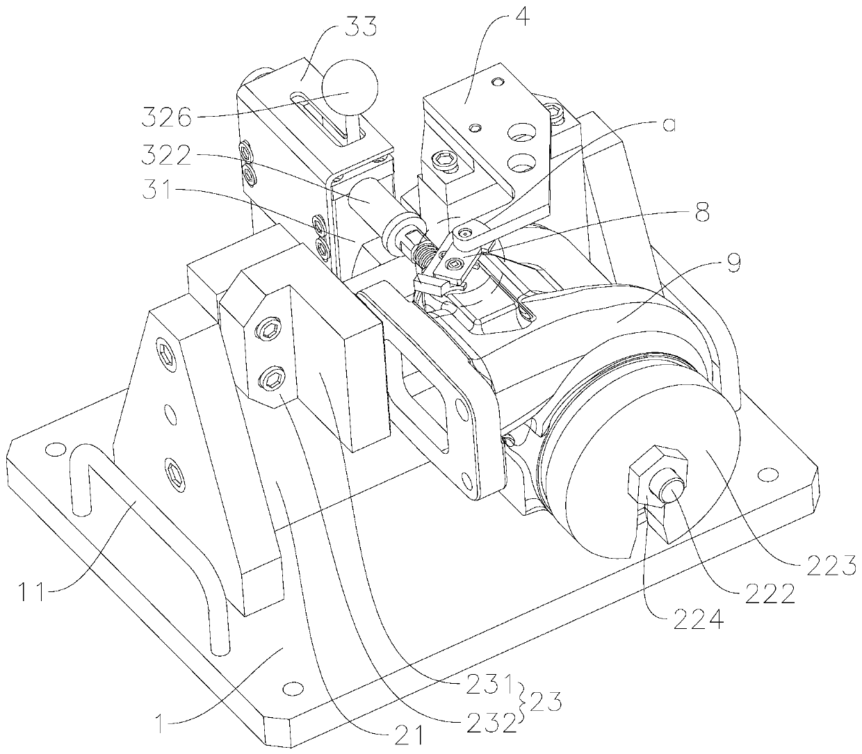
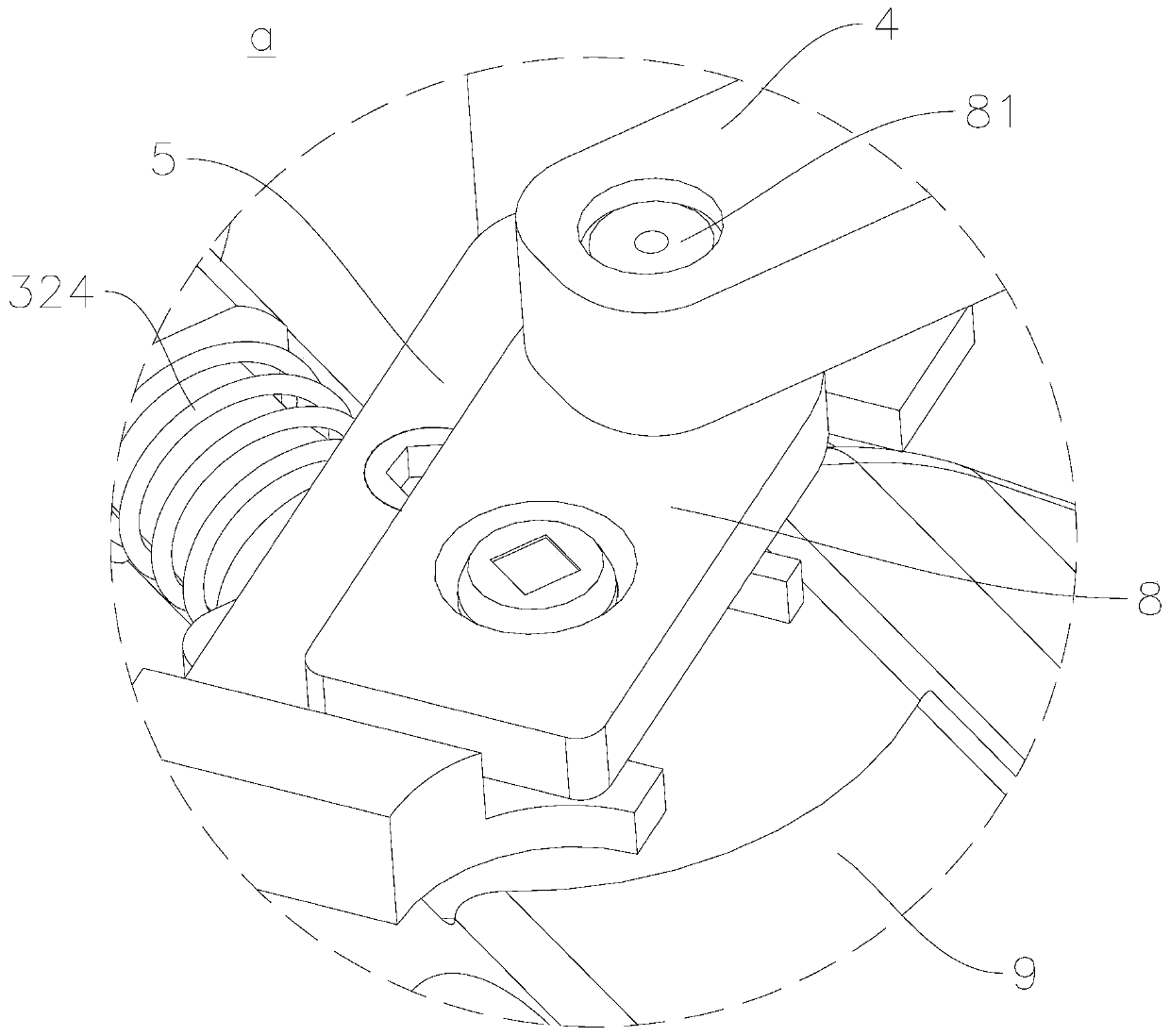
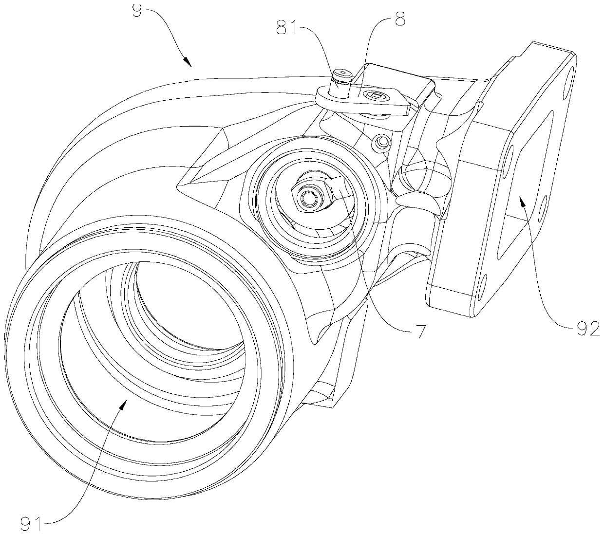
[0039] Such as Figure 1-Figure 8 As shown, a turbine casing rocker arm welding tool includes a bottom plate 1, a turbine casing fixing mechanism, a bypass valve limit mechanism and a rocker arm positioning plate 4, and the turbine casing fixing mechanism includes a supporting vertical plate 21 fixed on the bottom plate 1 and The positioning seat 22 and the limit plate 23 fixed on the support vertical plate 21; the bypass valve limit mechanism includes a limit support 31 fixed on the bottom plate 1 and a limit push rod 32 slidingly connected with the limit support 31 , the end of the limit push rod 32 has a limit pressure head 321 for controlling the up and down, left and right movement...


PUM


Abstract

The invention provides a welding fixture of a rocker arm of a turbine casing. The welding fixture comprises a bottom plate, a turbine casing fixing mechanism, a bypass valve limiting mechanism and a rocker arm locating plate. The turbine casing fixing mechanism comprises a supporting vertical plate fixed to the bottom plate, a locating seat and a limiting plate. The bypass valve limiting mechanismcomprises a limiting support fixed to the bottom plate and a limiting push rod, and a limiting press head is arranged at the end of the limiting push rod. The turbine casing is fixed to the locatingseat in a sleeve manner through a turbine casing center hole. The limiting plate and the outer side wall of a turbine casing runner opening cooperate to limit rotating of the turbine casing. The limiting push rod is pushed to the work position, and the limiting press head can press a bypass valve. One end of the rocker arm locating plate is fixed to the top of the supporting vertical plate, a locating hole is formed in the other end of the rocker arm locating plate, and a handle of the rocker arm is sleeved with the locating hole. The position of the turbine casing is fixed through the turbinecasing fixing mechanism, the bypass valve limiting mechanism is used for limiting swing of the bypass valve, precise locating is achieved, welding precision is guaranteed, and meanwhile the fixture is simple in mounting process and high in welding efficiency.

Description

technical field [0001] The invention belongs to the technical field of turbine shell rocker arm welding, and in particular relates to a turbine shell rocker arm welding tool. Background technique [0002] Turbine shell is the main part of turbocharger. The turbocharger with bypass valve can obviously improve the low-speed performance of the car, increase the low-speed torque, reduce the fuel consumption and pollution at low speed, and improve the performance of the engine at high speed. Indicators and use reliability. The turbocharger with a bypass valve needs to be equipped with a rocker arm operation room to control the bypass valve. When welding the rocker arm of the turbine shell, there are not only requirements for the clearance between the rocker arm and the bushing, but also extremely high requirements for the angle of the rocker arm. [0003] The existing welding tooling for the valve rocker arm assembly of the turbine shell, the process of fixing the turbine shell...

Claims


Application Information

Patent Timeline
Patent Type & Authority Applications(China)
IPC IPC(8): B23K37/04
CPCB23K37/0443
Inventor 孙艳芬朱国富董洪凯
Owner CHANGZHOU INST OF MECHATRONIC TECH
Learn More