Eureka AIR delivers breakthrough ideas for toughest innovation challenges, trusted by R&D personnel around the world.

Engine expansion section II section groove milling device

A technology of slot milling device and expansion section, which is applied in the field of slot milling device of engine expansion section II, which can solve the problems of increasing the weight of the slot milling device, difficulty in positioning the carcass, and containing hard metal particles, so as to reduce the processing cost and avoid Knife phenomenon, good machinability effect

Inactive Publication Date: 2020-05-08
XIAN SPACE ENGINE CO LTD
View PDF10 Cites 0 Cited by
  • Summary
  • Abstract
  • Description
  • Claims
  • Application Information

AI Technical Summary

Problems solved by technology

[0002] The key to the slot milling process of the engine expansion section is the fit between the parts and the positioning carcass. After more than half a century of development, this technology has become increasingly mature, but problems frequently occur during the processing and use of the slot milling device. The existing engine One of the defects of the expansion section milling device is that it is difficult to position the carcass in the device, and the material contains hard metal particles, which leads to the phenomenon of knife cutting; the second defect is that the positioning shaft is too long, which makes assembly difficult and increases the weight of the milling device; The third defect is spot welding at both ends of the lap joint plate. Due to different materials, it is difficult to weld, and the short support plate is damaged due to welding. When the material of the lap joint plate and short support plate is consistent with the parts, the cost will increase

Method used


Image

  • Engine expansion section II section groove milling device
  • Engine expansion section II section groove milling device

Examples


Embodiment Construction

[0026] The present invention will be further elaborated below in conjunction with embodiment.

[0027] The invention provides a slot milling device for the second section of the engine expansion section. It provides a small weight, easy to use, and low-cost engine expansion section II section milling device, which is specially used for the tire pressure, size, End removal allowance and milling process.

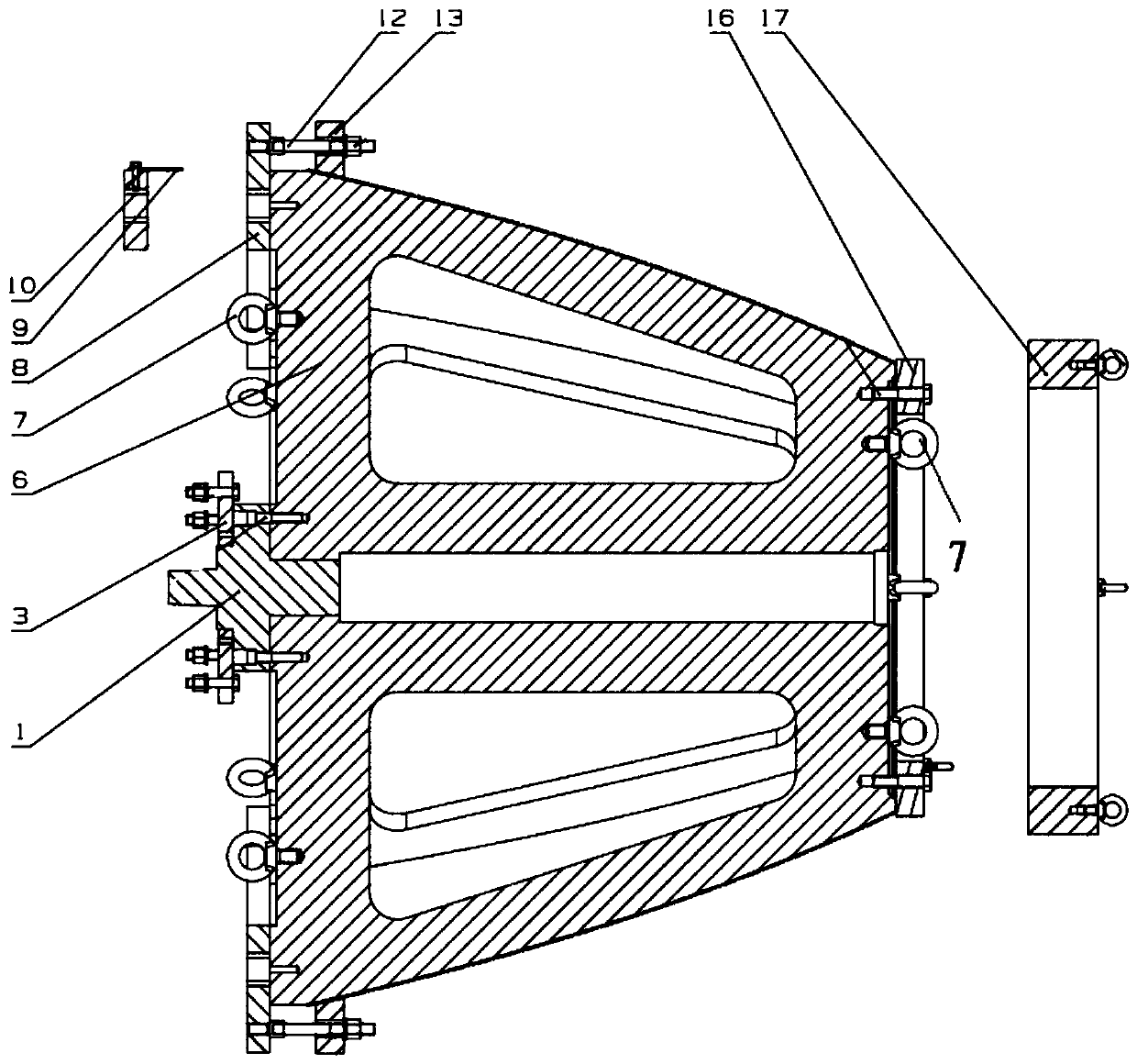
[0028] Such as figure 1 As shown, a milling device for engine expansion section II section mainly includes a tail handle 1, a connecting plate 3, a positioning carcass 6, an eyebolt screw 7, a long support plate 8, an overlapping plate 9, a short support plate 10, a double-head Stud 12, pressure ring 13, pressure plate 16 and large pressure ring 17; wherein, the positioning carcass 6 is a cone column segment structure; the axial large-diameter end and the small-diameter end of the positioning carcass 6 are all provided with eyebolt screws 7; 1 is fixedly installed at the axi...


PUM


Abstract

The invention relates to an engine expansion section II section groove milling device, and belongs to the field of groove milling device design. The engine expansion section II section groove millingdevice comprises a tail handle, a connecting plate, a positioning tire body, lifting ring screws, a long supporting plate, a lap joint plate, a short supporting plate, a double-end stud, a pressing ring, a pressing plate and a large pressing ring. The positioning tire body is of a conical column section structure, wherein the lifting ring screws are arranged at the axial large-diameter end and theaxial small-diameter end of the positioning tire body; the tail handle is fixedly arranged at the axis position of the axial large-diameter end of the positioning tire body; the connecting plate is of an annular structure and is fixedly arranged on the axial outer end face of the tail handle; the tail handle is fixedly connected with the positioning tire body through the connecting plate; the long supporting plate is of an annular structure and is coaxially and fixedly arranged at the axial large-diameter end of the positioning tire body; the pressing ring is of an annular structure; the double-end stud is arranged on the pressing ring in the circumferential direction; and the double-end stud is axially perpendicular to the pressing ring. The engine expansion section II section groove milling device has the beneficial effects of being small in weight, low in cost, high in practicability and the like.

Description

technical field [0001] The invention belongs to the design field of slot milling devices, and relates to a slot milling device for engine expansion section II. Background technique [0002] The key to the slot milling process of the engine expansion section is the fit between the parts and the positioning carcass. After more than half a century of development, this technology has become increasingly mature, but problems frequently occur during the processing and use of the slot milling device. The existing engine One of the defects of the expansion section milling device is that it is difficult to position the carcass in the device, and the material contains hard metal particles, which leads to the phenomenon of knife cutting; the second defect is that the positioning shaft is too long, which makes assembly difficult and increases the weight of the milling device; The third defect is spot welding at both ends of the lap joint plate, which is difficult to weld due to differen...

Claims


Application Information

Patent Timeline
IPC IPC(8): B23P15/00B23C3/28B23Q3/06
CPCB23C3/28B23P15/00B23Q3/062
Inventor 王东贺崇森陈磊许桐晔李红丽
Owner XIAN SPACE ENGINE CO LTD
Why Eureka
Eureka Blog
Learn More