Artificial intelligence automatic obstacle avoidance walking chassis

A technology of automatic obstacle avoidance and walking chassis, which is applied in the direction of non-electric variable control, substructure, elastic suspension, etc., and can solve the problems of large volume, large mass, inconvenience, etc.

Active Publication Date: 2020-05-08
中科南京人工智能创新研究院 +1
View PDF12 Cites 4 Cited by
  • Summary
  • Abstract
  • Description
  • Claims
  • Application Information

AI Technical Summary

Problems solved by technology

[0002] With the development of existing industrial technology and the continuous innovation of the level of mechanization, high-tech heavy industrial equipment replaces traditional production industrial equipment, but when these equipment are transferred to the workshop, large-scale hoisting equipment is not convenient to enter the workshop, and the space in the workshop is not convenient for hoisting equipment Lifting, it is not easy to move into the workshop. In the existing technology, a small mobile chassis is installed at the bottom of the equipment to assist the movement.

Method used


Image

  • Artificial intelligence automatic obstacle avoidance walking chassis
  • Artificial intelligence automatic obstacle avoidance walking chassis
  • Artificial intelligence automatic obstacle avoidance walking chassis

Examples


Embodiment 1

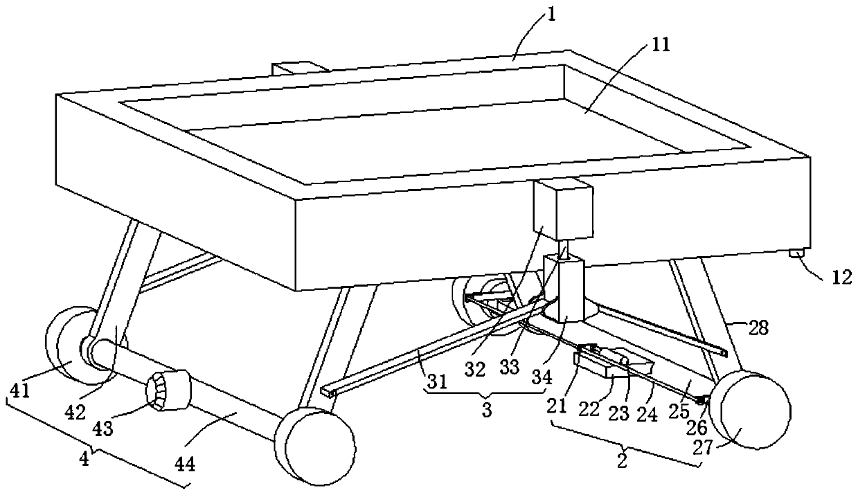
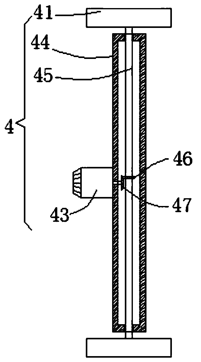
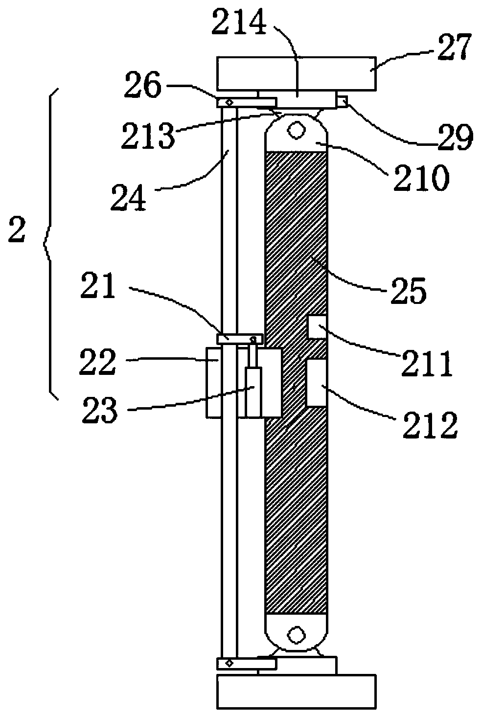
[0030] see Figure 1-5 , this embodiment provides an artificial intelligence automatic obstacle avoidance walking chassis, including a chassis 1, a data processing module 5, a driving mechanism 4, a steering mechanism 2 and two adjustment mechanisms 3, and the driving mechanism 4 includes two first hinged rods 42. The first rotating sleeve 44, the driving motor 43 and the two power wheels 41. The top surfaces of the two first articulated rods 42 of the driving mechanism 4 are respectively hinged on the front and rear sides of the left end of the bottom surface of the chassis 1. The steering mechanism 2 includes There are two second articulated rods 28, a second rotating sleeve 25, an electric hydraulic cylinder 23, a transmission rod 24 and two steering wheels 27, and the top surfaces of the two second articulated rods 28 of the steering mechanism 2 are respectively hinged on the chassis 1 The two adjustment mechanisms 3 include a servo motor 32, a threaded rod 33, a rectangul...

Embodiment 2

[0036] see Figure 1-5 , made further improvement on the basis of embodiment 1:

[0037] The top surface of the chassis 1 is provided with a rectangular placement groove 11. By opening the rectangular placement groove 11, it is convenient to match the bottom corner side wall of the receiving equipment, so as to facilitate the auxiliary movement of the equipment;

Embodiment 3

[0039] see Figure 1-5 , made further improvement on the basis of embodiment 1:

[0040] Each servo motor 32 is respectively connected with each threaded rod 33 through a power shaft, and each rectangular lifting seat 34 is provided with a threaded hole running through the upper and lower end faces of the rectangular lifting seat 34, and each threaded rod 33 is connected with each rectangular lifting seat through external threads respectively. The threaded hole inner cavity of seat 34 is rotated and plugged in, and the left and right end surface bottoms of each rectangular lifting seat 34 are hinged with the tops of two pull rods 31 respectively, and the tips of two pull rods 31 are respectively connected with the first hinged rod 42 and the second hinged rod. The bottom of the outer wall of 28 is hinged; the bottom end face of the chassis 1 is embedded with a height sensor 12 in the right front face, and the signal output port of the height sensor 12 is connected with the sig...


PUM


Abstract

The invention discloses an artificial intelligence automatic obstacle avoidance walking chassis, which comprises a chassis, a data processing module, a driving mechanism, a steering mechanism and twoadjusting mechanisms, wherein the driving mechanism comprises two first hinge rods, a first rotating sleeve, a driving motor and two power wheels; the top end faces of two first hinge rods of the driving mechanism are hinged to the front and rear sides of the left end of the bottom end face of the chassis respectively; the steering mechanism comprises two second hinge rods, a second rotating sleeve, an electric hydraulic cylinder, a transmission rod and two steering wheels; the top end faces of two second hinge rods of the steering mechanism are hinged to the front side and the rear side of the right end of the bottom end face of the chassis respectively; each adjusting mechanism comprises a servo motor, a threaded rod, a rectangular lifting seat and two pull rods; and the servo motors ofthe two adjusting mechanisms are fixedly installed in the middle sections of the front end face and the rear end face of the chassis respectively. By automatically controlling the moving direction, obstacles can be conveniently and automatically avoided, and large equipment can be conveniently assisted in moving.

Description

technical field [0001] The invention relates to the related technical field of artificial intelligence walking chassis, in particular to an artificial intelligence automatic obstacle avoidance walking chassis. Background technique [0002] With the development of existing industrial technology and the continuous innovation of the level of mechanization, high-tech heavy industrial equipment replaces traditional production industrial equipment, but when these equipment are transferred to the workshop, large-scale hoisting equipment is not convenient to enter the workshop, and the space in the workshop is not convenient for hoisting equipment Lifting, it is not easy to move into the workshop. In the existing technology, a small mobile chassis is installed at the bottom of the equipment to assist the movement. Due to the large size and mass of the equipment, it is difficult to control the direction of movement due to the large volume and mass of the equipment. , During the movin...

Claims


Application Information

Patent Timeline
IPC IPC(8): B62D21/18B62D5/12B62D7/20B60B35/12B60G17/015G05D1/02
CPCB60B35/122B60G17/0157B60G2500/30B62D5/12B62D7/20B62D21/18G05D1/024G05D1/0242
Inventor 胡庆浩王培松李成华辛淼程健
Owner 中科南京人工智能创新研究院
Why Eureka
Try Eureka