Installation device facilitating movement and levelness adjustment of machine
A technology of mechanical equipment and level adjustment, which is applied in the direction of transportation and packaging, metal processing equipment, conveyor objects, etc., to achieve the effect of convenient level adjustment and convenient movement
- Summary
- Abstract
- Description
- Claims
- Application Information
AI Technical Summary
Problems solved by technology
Method used
Image
Examples
Embodiment 1
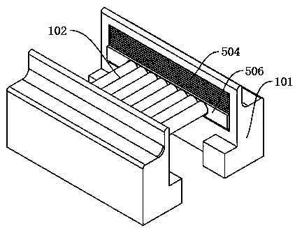
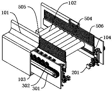
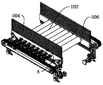
[0026] An installation device that facilitates the movement and level adjustment of mechanical equipment, including: a support frame 101 and a roller 102, the support frame 101 is arranged on the left and right sides of the roller 102, and the inside of the support frame 101 is sequentially provided with a driving compartment 103 and a Rotating warehouse 104, the bottom of the front and rear sides of the rotating warehouse 104 is fixedly equipped with a linkage mechanism. The inner side of the upper end is fixedly connected with the steering mechanism, the middle part of the horizontal mechanism is movably connected with the inner end of the rotating mechanism, the upper and lower ends of the horizontal mechanism are movably socketed inside the supporting frame 101, and the inner end of the steering mechanism is fixed to the left and right ends of the roller 102 connect.
[0027] The present invention drives the transmission mechanism to run through the linkage mechanism provi...
Embodiment 2
[0028] Embodiment 2: Based on Embodiment 1, the difference is:
[0029] The linkage mechanism comprises: servo motor 201, rotating ratchet 202, rotating gear 203, outer one-way rotating wheel set 204, inner one-way rotating wheel set 205, rotating shaft 206, rotating bushing 207 and transmission shaft 208, on the servo motor 201 main shaft The axis of the rotating ratchet 202 is fixedly connected with the lower end of the outer one-way rotating wheel set 204 in sequence, the upper side of the rotating ratchet 202 is fixedly connected with the lower end of the rotating gear 203, and the axis of the rotating gear 203 is fixedly connected with the inner end of the transmission shaft 208. The outer end of the shaft 208 is fixedly connected with the center of the lower end of the inner one-way rotating wheel set 205, the middle part of the transmission shaft 208 is movably connected with the inner wall of the support frame 101, and the upper end axis of the inner one-way rotating wh...
Embodiment 3
[0033] Embodiment 3: Based on Embodiment 1 and 2, but the difference is:
[0034] The horizontal mechanism includes: a lower steering rod 501, an upper steering rod 502, a moving block 503, a telescopic moving curtain 504 and a movable groove 505, the inner end of the rotating shaft 206 is fixedly connected with the lower end of the lower steering rod 501, and the upper end of the lower steering rod 501 is connected with the upper steering rod. The lower end of the rod 502 is movably connected, the upper end of the upper steering rod 502 is fixedly connected with the front and rear ends of the moving block 503, the upper and lower ends of the moving block 503 are fixedly connected with the telescopic moving curtain 504, and the upper and lower ends of the inner side of the steering bin 104 are provided with movable grooves 505 The upper and lower ends of the telescopic mobile curtain 504 are movably socketed inside the movable groove 505, and the inner side of the cross knuckle...
PUM
 Abstract
Description
Claims
Application Information
 - R&D
- Intellectual Property
- Life Sciences
- Materials
- Tech Scout
- Unparalleled Data Quality
- Higher Quality Content
- 60% Fewer Hallucinations
Browse by: Latest US Patents, China's latest patents, Technical Efficacy Thesaurus, Application Domain, Technology Topic, Popular Technical Reports.
© 2025 PatSnap. All rights reserved.Legal|Privacy policy|Modern Slavery Act Transparency Statement|Sitemap|About US| Contact US: help@patsnap.com


