
Pollutant suction system applied to vacuum toilet

A vacuum and toilet technology, applied in applications, waterway systems, sewage discharge, etc., can solve problems such as inability to replenish vacuum in time, incomplete suction of sewage, and inability to suck away.

Pending Publication Date: 2020-05-08
CHENGDU QIANJI ENTERPRISE MANAGEMENT CONSULTING CO LTD
View PDF0 Cites 0 Cited by
  • Summary
  • Abstract
  • Description
  • Claims
  • Application Information

AI Technical Summary

Problems solved by technology

[0009] In order to overcome the deficiencies of the prior art, the present invention provides a sewage suction system applied to vacuum toilets, which solves the problem that the existing vacuum negative pressure tanks tend to weaken the suction capacity and cannot replenish the vacuum in time, resulting in incomplete suction and even poor suction. The situation of not going away occurs, and at the same time, the existing vacuum negative pressure tank has high requirements on the vacuum pump and power supply environment, making it impossible to truly promote and popularize the use of vacuum toilets

Method used


Image

  • Pollutant suction system applied to vacuum toilet
  • Pollutant suction system applied to vacuum toilet
  • Pollutant suction system applied to vacuum toilet

Examples


Embodiment 1

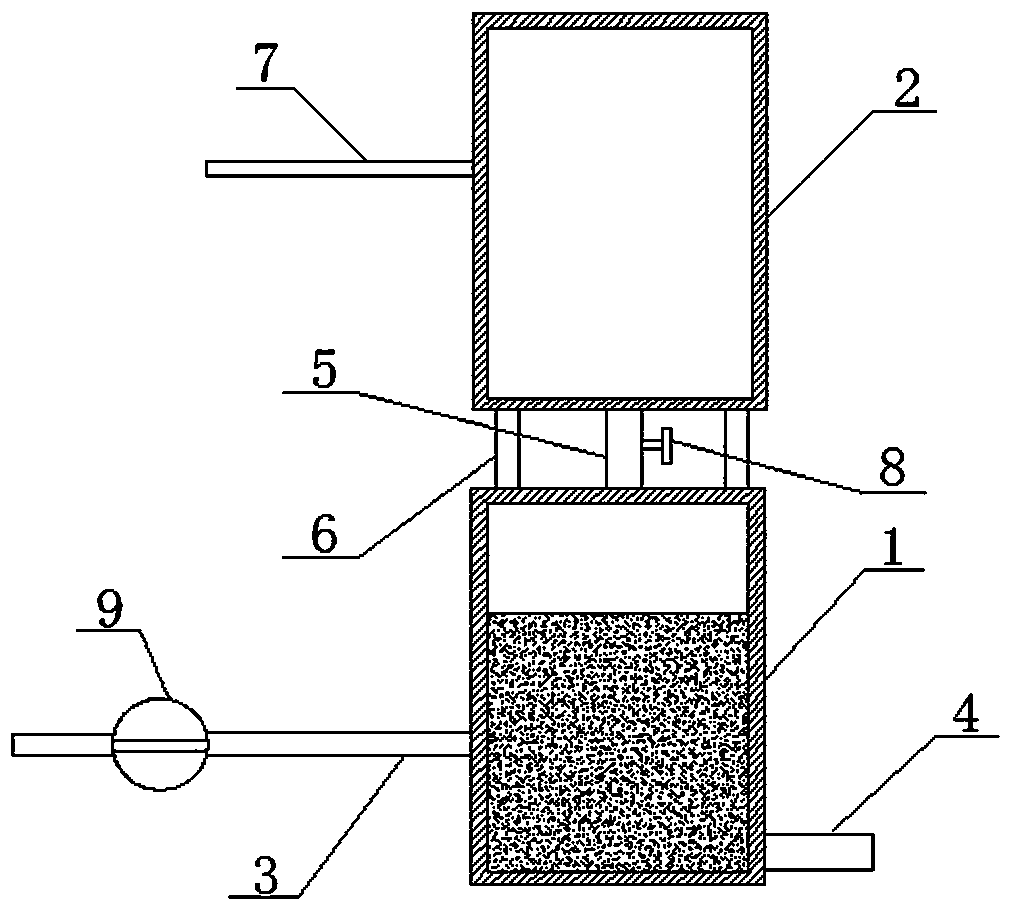
[0038] Such as figure 1 As shown, a sewage suction system applied to a vacuum toilet shown in a preferred embodiment of the present invention includes two vacuum negative pressure tanks that realize air pressure communication through the pressure guiding pipe 5, and one of the vacuum negative pressure tanks is used for suction The adsorption tank 1 for dirt and temporary storage of dirt, and another vacuum negative pressure tank is used as a pressure supply tank 2 for providing vacuum negative pressure to the adsorption tank 1, and the pressure guiding pipe 5 is provided with a constant pressure device 8, and the The adsorption tank 1 is provided with a sewage inlet pipe 3 for inhaling dirt and a sewage discharge pipe 4 for discharging dirt. The sewage inlet pipe 3 is provided with a vacuum shut-off valve 9. The pressure supply tank 2 is provided with a Air extraction pipe 7 for extracting air.

[0039] In the present embodiment, taking the vacuum toilet as an example, the fa...


PUM


Abstract

The invention discloses a pollutant suction system applied to a vacuum toilet. The system comprises two vacuum negative pressure tanks which are in air pressure communication through a connecting pipe, one vacuum negative pressure tank is an adsorption tank used for sucking pollutants and temporarily storing the pollutants, the other vacuum negative pressure tank is a pressure supply tank for supplying vacuum negative pressure to the adsorption tank, a constant pressure device is arranged on the connecting pipe, a pollutant inlet pipe used for sucking the pollutants and a pollutant dischargingpipe used for discharging pollutants are arranged on the adsorption tank, a vacuum stop valve is arranged on a pollutant inlet pipe, and an exhausting pipe used for extracting air is arranged on thepressure supply tank. With the adoption of the structure, the adsorption tank can always keep higher pollutant adsorption capability, requirements for the power supply environment are reduced, and thevacuum toilet can be really promoted and popularized.

Description

technical field [0001] The invention relates to the field of vacuum negative pressure tanks, in particular to a sewage suction system applied to vacuum toilets. Background technique [0002] Vacuum toilet is a kind of toilet. Through the air pressure difference generated by the flushing system, the dirt in the toilet is sucked away in the form of air suction, so as to achieve the purpose of reducing the use of flushing water, which can greatly save flushing water. National regulations The traditional water-saving toilet is 6L / time, but after adopting the vacuum public toilet, each flushing of the toilet is <0.8L / time, which completely solves the odor problem of the toilet with small space and poor air circulation. At present, vacuum toilets are mostly found in environments lacking flushing water, such as civil aviation airliners, cruise ships, and passenger trains. [0003] One of the important components of the vacuum toilet is the vacuum negative pressure tank. As the ...

Claims


Application Information

Patent Timeline
Patent Type & Authority Applications(China)
IPC IPC(8): E03F1/00A47K11/00
CPCE03F1/006A47K11/00
Inventor 仰国其
Owner CHENGDU QIANJI ENTERPRISE MANAGEMENT CONSULTING CO LTD
Learn More