
Double-plunger supercharger

A supercharger, double plunger technology, used in fluid pressure converters, mechanical equipment, etc., can solve the problems of inability to guarantee continuity, high cost, high pressure pulsation, etc., to avoid electrical instability factors, save space and parts , the effect of long working life

Active Publication Date: 2020-05-08
宁波真格液压科技有限公司
View PDF14 Cites 0 Cited by
  • Summary
  • Abstract
  • Description
  • Claims
  • Application Information

AI Technical Summary

Problems solved by technology

The single-plunger supercharger cannot guarantee the continuity of the pressure output, and cannot meet many high-pressure work requirements. Although the double-plunger reciprocating supercharger can achieve continuous pressure output, the output pressure is zero at the moment of reversing, making the output The high pressure produces pulsation, which cannot be used in some occasions requiring constant pressure; although there are two-cylinder four-plunger boosters on the market, such as a four-plunger hydraulic booster with application number 201810417249.0, it is used to control The first pressurized cylinder and the second pressurized cylinder operate continuously, using two pistons to control the direction of each other’s oil passages, which includes complex oil passages, complex control, complex structure, large volume, and high cost; and because of its The control is complicated and the oil circuit is complicated. When a fault occurs, it is not only difficult to troubleshoot the problem, but also inconvenient to maintain

Method used


Image

  • Double-plunger supercharger
  • Double-plunger supercharger
  • Double-plunger supercharger

Examples


Embodiment Construction

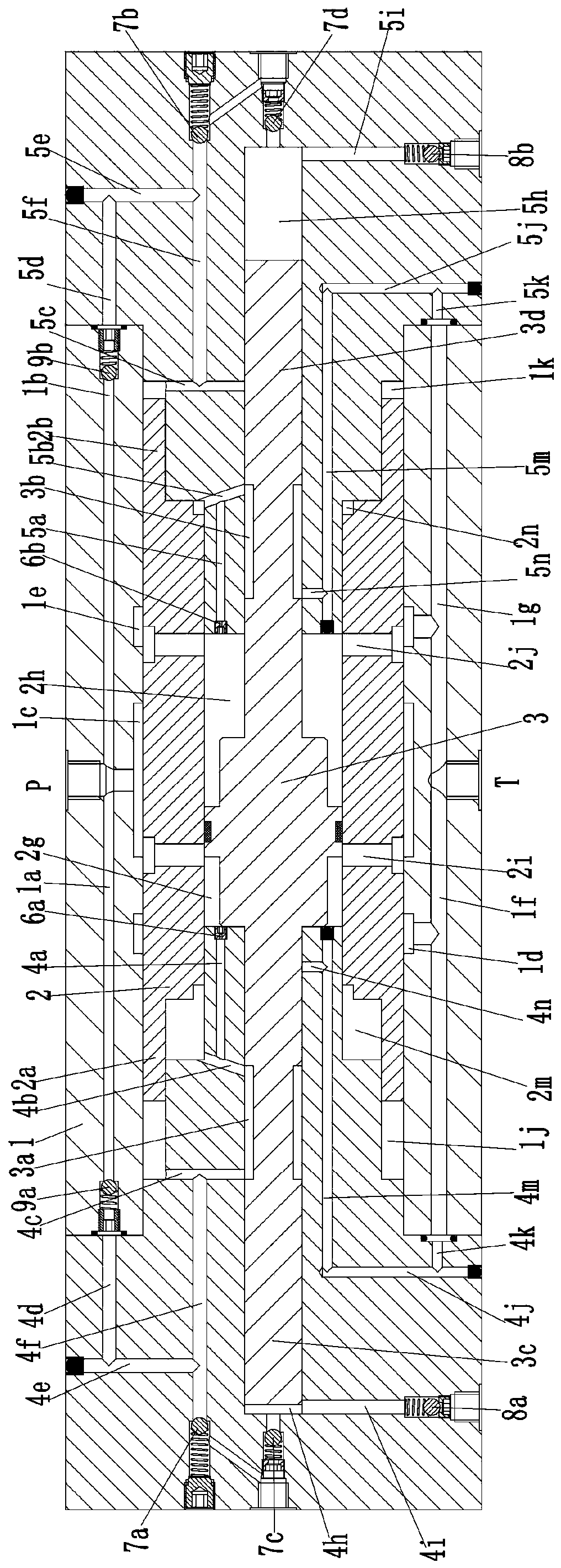
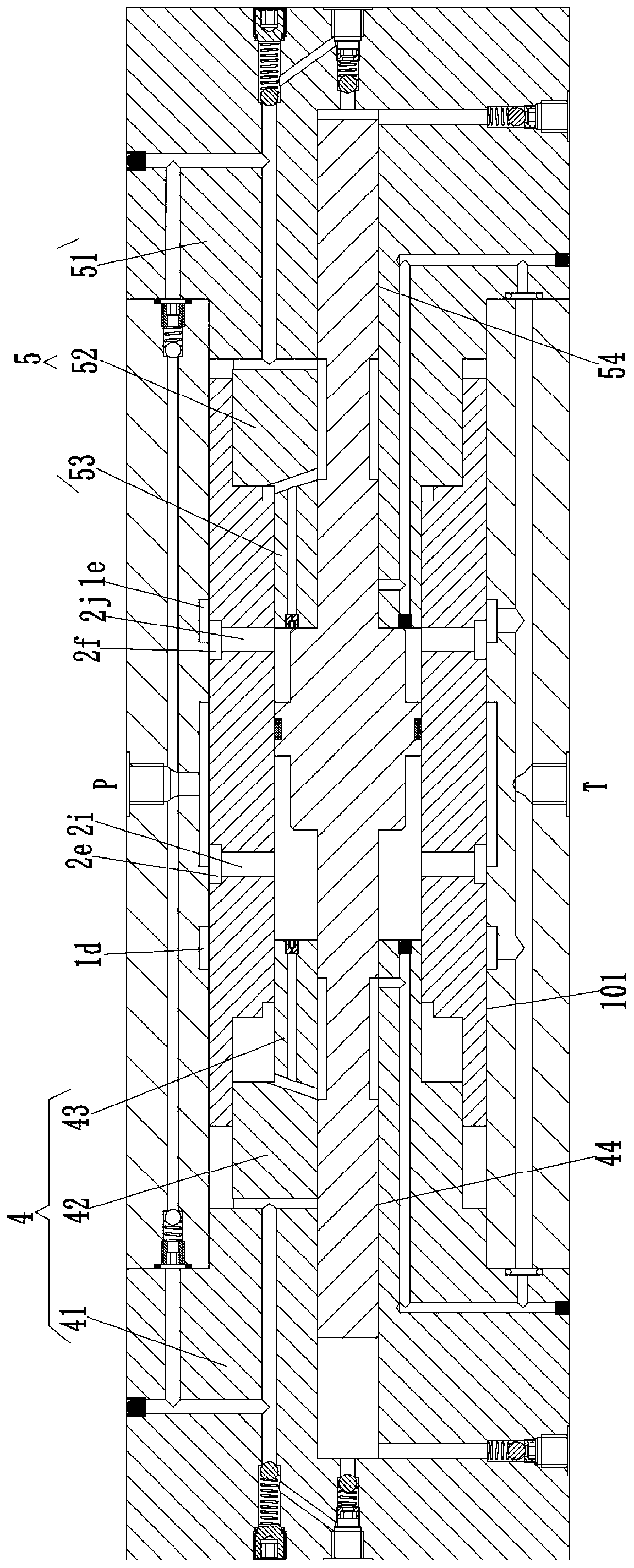
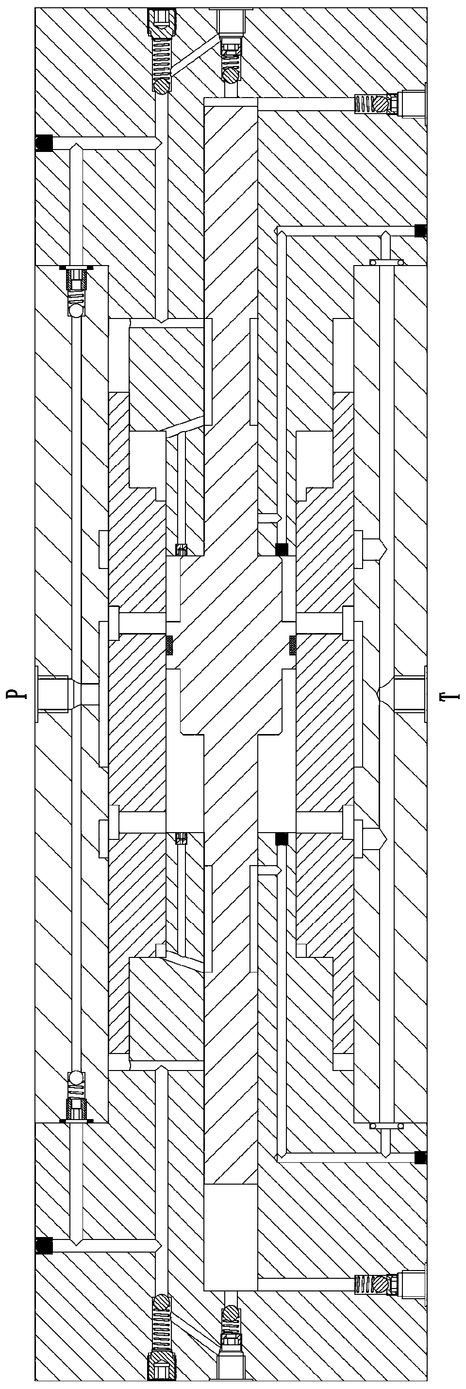
[0024] see Figure 1-4 As shown, a double-plunger supercharger includes a body 1, the body 1 is provided with a mounting hole 101 penetrating left and right, and the side of the body 1 is provided with a P port and a T port communicating with the mounting hole 101; The left side of the body 1 is fixedly installed with a left end cover 4 at the left end of the installation hole 101, and the right side of the body 1 is fixedly installed with a right end cover 5 at the right end of the installation hole 101; On the left body 41, the left body 41 is provided with a left post 42 extending into the mounting hole 101, and the right end of the left post 42 extends axially along the mounting hole 101 with a left two post 43, The right end cover 5 includes a right body 51 installed on the body 1, the right body 51 is provided with a right protrusion 52 extending into the installation hole 101, and the left end of the right protrusion 52 is along the axis of the installation hole 101. T...


PUM


Abstract

The invention discloses a double-plunger supercharger. The double-plunger supercharger comprises a machine body, wherein a mounting hole is formed in the machine body; a port P and a port T which communicate with the mounting hole are formed in the side surface of the machine body; a left end cover is mounted on the left side of the machine body, and a right end cover is mounted on the right sideof the machine body; the left end cover comprises a left body; a left first convex column is arranged on the left body; a left second convex column is arranged at the right end of the left first convex column; the right end cover comprises a right body; a right first convex column is arranged on the right body; a right second convex column is arranged at the left end of the right first convex column; a cylinder sleeve is slidably connected in the mounting hole; a power piston is slidably connected in the cylinder sleeve; a left piston cavity is formed between the left end of the power piston and the left second convex column in the cylinder sleeve, and a right piston cavity is formed between the right end of the power piston and the right second convex column in the cylinder sleeve; a leftpump assembly is arranged in the left end cover; and a right pump assembly is arranged in the right end cover. The double-plunger supercharger is highly integrated in integral design, space and partsare saved, moreover, oil ways are reduced, control is simple, and in addition, electric control is not required.

Description

technical field [0001] The invention belongs to the technical field of superchargers, and in particular relates to a four-piston supercharger. Background technique [0002] The superchargers currently used in the market are mainly traditional single-plunger superchargers and double-plunger reciprocating superchargers. The single-plunger supercharger cannot guarantee the continuity of the pressure output, and cannot meet many high-pressure work requirements. Although the double-plunger reciprocating supercharger can achieve continuous pressure output, the output pressure is zero at the moment of reversing, making the output The high pressure produces pulsation, which cannot be used in some occasions requiring constant pressure; although there are two-cylinder four-plunger boosters on the market, such as a four-plunger hydraulic booster with application number 201810417249.0, it is used to control The first pressurized cylinder and the second pressurized cylinder operate cont...

Claims


Application Information

Patent Timeline
Patent Type & Authority Applications(China)
IPC IPC(8): F15B3/00
CPCF15B3/00
Inventor 邵立坤其他发明人请求不公开姓名
Owner 宁波真格液压科技有限公司
Learn More