Temperature equalization plate and preparation method thereof
A technology of vapor chamber and cover plate, which is applied in the direction of lighting and heating equipment, indirect heat exchangers, etc., which can solve the problems of further improvement of heat dissipation performance, complicated preparation process, and complex structure, and achieve simple structure, simple process, and heat dissipation. good effect
- Summary
- Abstract
- Description
- Claims
- Application Information
AI Technical Summary
Problems solved by technology
Method used
Image
Examples
Embodiment 1
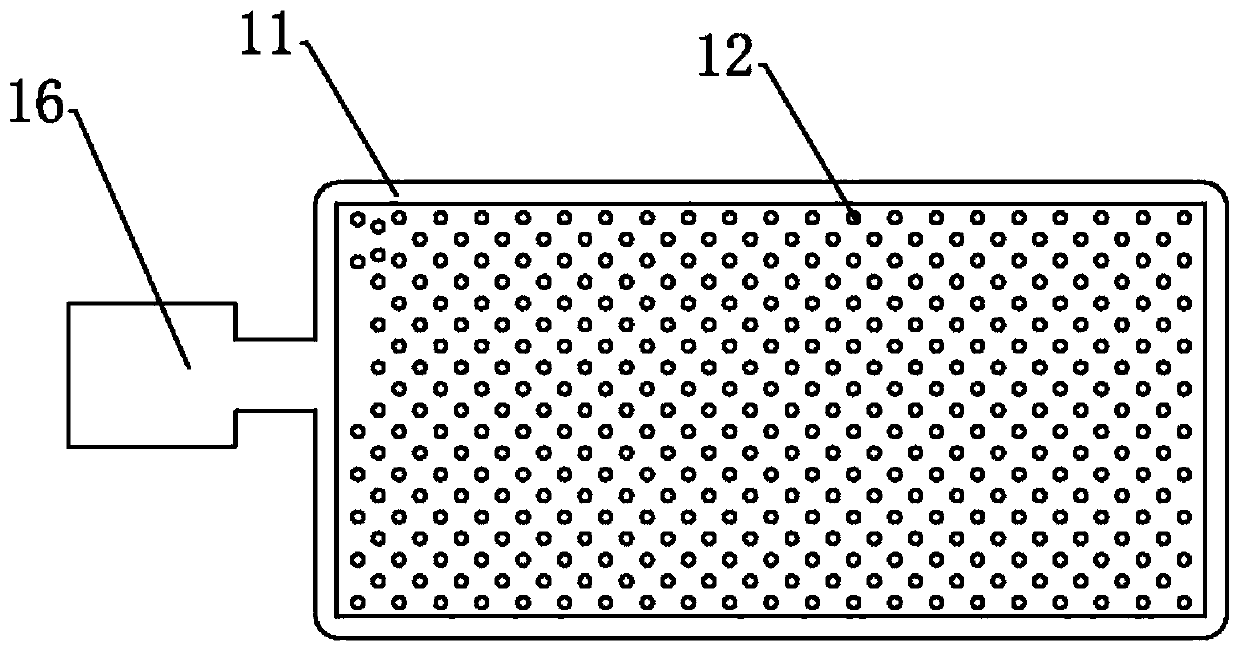
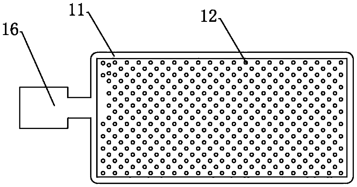
[0039] A temperature chamber, comprising an upper cover plate 13 and a lower cover plate 14 connected to the upper cover plate 13, the upper cover plate 13 and the lower cover plate 14 surround and form a hollow chamber, and the hollow chamber is used to accommodate A working fluid is provided, and a capillary structure is provided in the chamber.
[0040] Further, the lower cover plate 14 includes a base plate and a frame 11 surrounding the periphery of the base plate, and the base plate, the frame 11 and the upper cover plate surround to form a hollow chamber.
[0041]Further, the capillary structure is disposed on the lower cover 14 , and the capillary structure is attached to the inner surface of the substrate. The capillary structure includes a base layer and a protrusion 12 protruding from the base layer, and the base layer is attached to the inner surface of the lower cover plate 14 .
[0042] Further, a plurality of supporting protrusions 15 are arranged in the chambe...
Embodiment 2
[0063] A temperature chamber, comprising an upper cover plate 13 and a lower cover plate 14 connected to the upper cover plate 13, the upper cover plate 13 and the lower cover plate 14 surround and form a hollow chamber, and the hollow chamber is used to accommodate A working fluid is provided, and a capillary structure is provided in the chamber.
[0064] Further, the lower cover 14 includes a base plate and a frame 11 surrounding the periphery of the base plate, and the base plate, the frame 11 and the upper cover plate surround to form a hollow chamber.
[0065] Further, the capillary structure is divided into a first capillary structure disposed on the upper cover 13 and a second capillary structure disposed on the lower cover 14 . The first capillary structure is attached to the inner surface of the upper cover 13 . The second capillary structure is attached to the inner surface of the substrate.
[0066] Further, the capillary structure includes a base layer and a prot...
Embodiment 3
[0085] The difference between this embodiment and Embodiment 1 is that in this embodiment, the capillary structure is arranged on the upper cover plate 13 .
[0086] A method for preparing the above-mentioned vapor chamber, comprising the steps of:
[0087] (1) Get the sheet metal and process it into the required shape according to the specifications of the upper cover plate 13 and the lower cover plate 14;
[0088] (2) Electroplating or sintering the capillary structure on the upper cover plate 13 and the lower cover plate 14;
[0089] (3) Flux the upper cover plate 13 and the lower cover plate 14, and reserve the liquid inlet of the working fluid;
[0090] (4) Vacuumize through the liquid inlet and inject the working fluid;
[0091] (5) Seal the liquid inlet to obtain a vapor chamber.
[0092] Further, both the upper cover plate 13 and the lower cover plate 14 are provided with supporting bosses 15 .
[0093] Further, in the step (2), electroplating the capillary structure...
PUM
| Property | Measurement | Unit |
|---|---|---|
| surface roughness | aaaaa | aaaaa |
| thickness | aaaaa | aaaaa |
Abstract
Description
Claims
Application Information
 - R&D
- Intellectual Property
- Life Sciences
- Materials
- Tech Scout
- Unparalleled Data Quality
- Higher Quality Content
- 60% Fewer Hallucinations
Browse by: Latest US Patents, China's latest patents, Technical Efficacy Thesaurus, Application Domain, Technology Topic, Popular Technical Reports.
© 2025 PatSnap. All rights reserved.Legal|Privacy policy|Modern Slavery Act Transparency Statement|Sitemap|About US| Contact US: help@patsnap.com


