Robot joint mapping method and device and computer readable storage medium

A technology for robotics and mapping, applied in the field of robotics, can solve problems such as the inability of mapping to meet demand, and achieve the effect of improving synergy and optimizing the mapping process

Inactive Publication Date: 2020-05-08
JUXING TECH SHENZHEN CO LTD
View PDF5 Cites 13 Cited by
  • Summary
  • Abstract
  • Description
  • Claims
  • Application Information

AI Technical Summary

Problems solved by technology

[0006] It can be seen that in the actual application scenario, the user of the robot hopes to change the location environment into a known environment as soon as possible. Moreover, when targeting a large-scale application scenario, one machine cannot satisfy the demand. At this time, It is also necessary to use multi-robots for joint mapping. At present, there is no efficient and accurate multi-robot joint mapping scheme

Method used


Image

  • Robot joint mapping method and device and computer readable storage medium
  • Robot joint mapping method and device and computer readable storage medium
  • Robot joint mapping method and device and computer readable storage medium

Examples


Embodiment 1

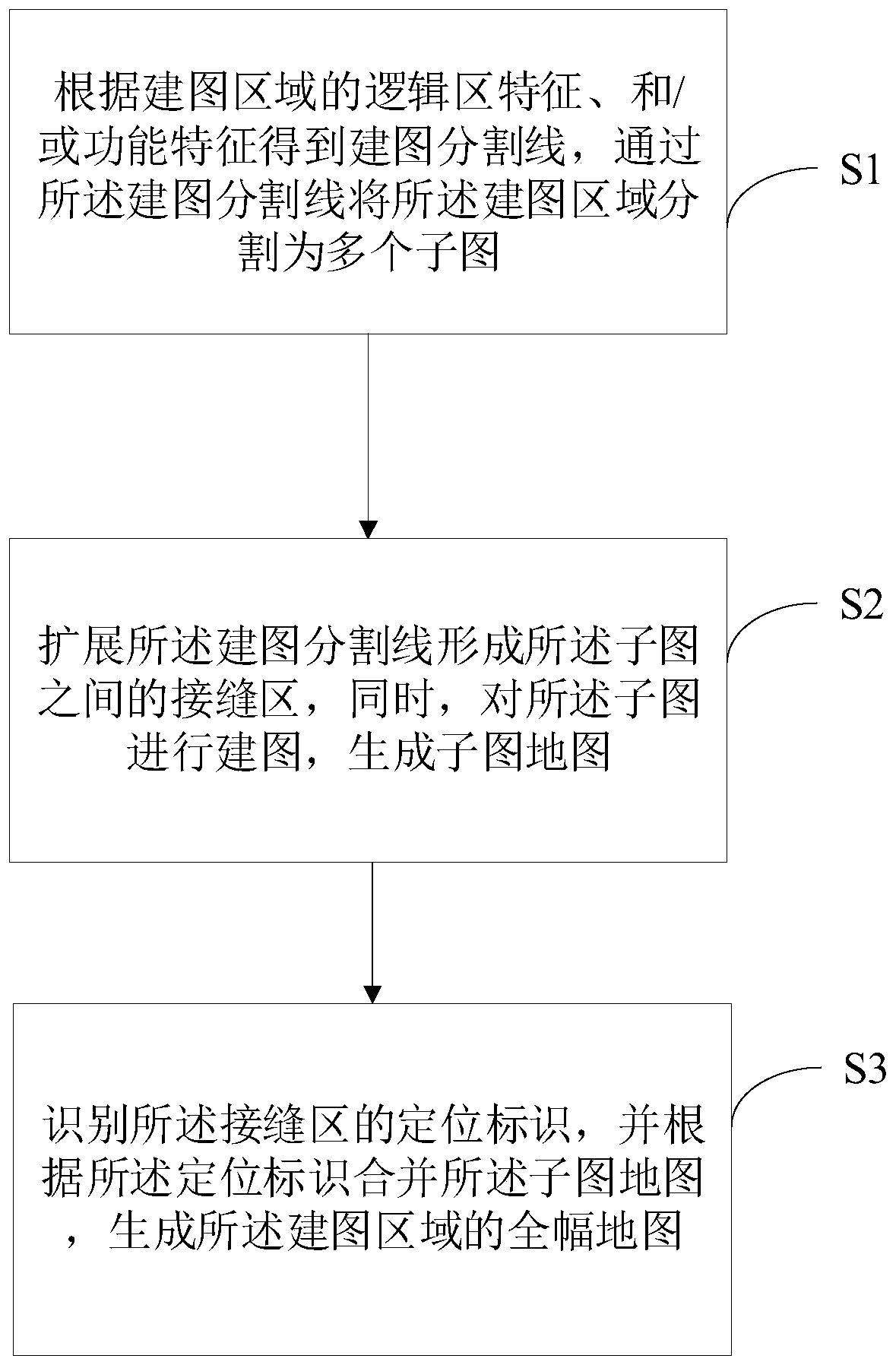
[0048] figure 1 It is the first flow chart of the robot joint mapping method provided by the embodiment of the present invention. This embodiment proposes a robot joint mapping method, the method comprising:

[0049] S1. Obtain a mapping dividing line according to the logical area characteristics and / or functional characteristics of the mapping area, and divide the mapping area into multiple sub-graphs through the mapping dividing line;

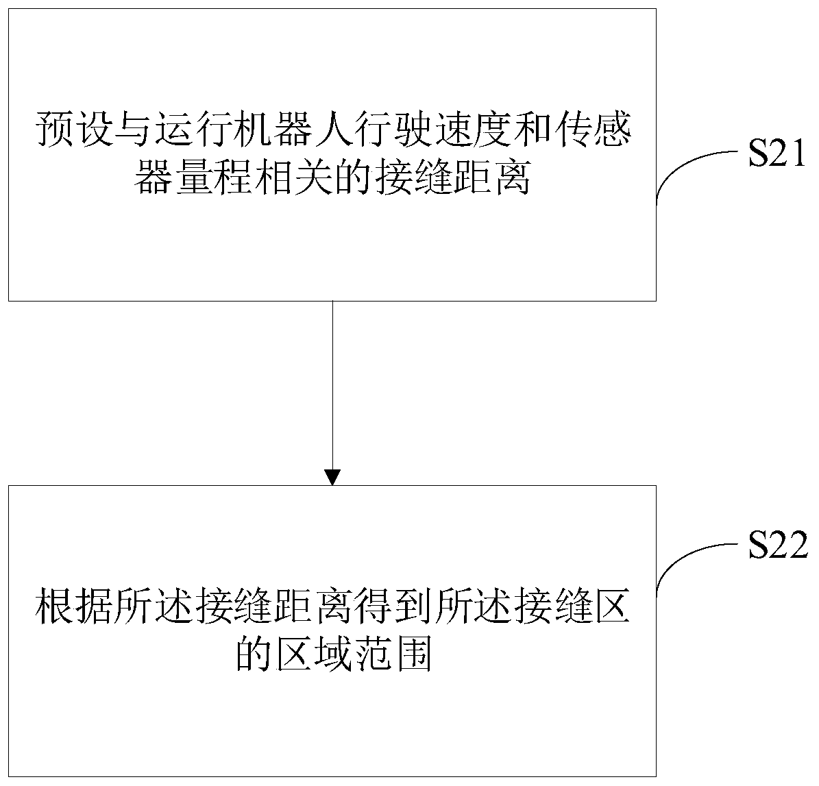
[0050] S2. Expand the mapping dividing line to form a seam area between the sub-graphs, and at the same time, perform mapping on the sub-graphs to generate a sub-graph map;

[0051] S3. Identify the positioning mark of the seam area, and merge the submap maps according to the positioning mark to generate a full map of the mapping area.

[0052] In this embodiment, firstly, a mapping division line is obtained according to the logical area characteristics and / or functional characteristics of the mapping area, and the mapping area is divided int...

Embodiment 2

[0057] Based on the above embodiment, in order to ensure that the perception error of each mapping robot for the environment of the mapping area is controlled within an acceptable range, in this embodiment, the sensor information of the robot will be calibrated according to the preset mapping measurement standard.

[0058] Specifically, it is first necessary to clarify the calibration scheme for each mapping robot in this embodiment, that is, use the same scene to establish a measurement standard, and on this basis, each individual mapping machine corrects itself according to the measurement standard to obtain data, so as to ensure that the perception error of each mapping robot for the environment of the mapping area is controlled within an acceptable range.

[0059] Then, determine the sensor solution adopted by each mapping robot in this embodiment. Among them, the common indoor solution sensors are as follows: Odom mechanical odometer, Imu (Inertialmeasurementunit) inertia...

Embodiment 3

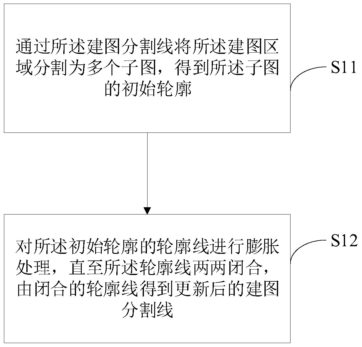
[0067] figure 2 It is the second flow chart of the robot joint mapping method provided by the embodiment of the present invention. Based on the above embodiment, in this embodiment, the mapping division line is obtained according to the logical area characteristics and / or functional characteristics of the mapping area, and the mapping area is divided into multiple sub-sections by the mapping division line. Figures, including:

[0068] S11. Divide the mapping area into a plurality of sub-graphs by using the mapping dividing line to obtain the initial outline of the sub-graphs;

[0069] S12. Perform expansion processing on the contour lines of the initial contour until the contour lines are closed in pairs, and an updated mapping dividing line is obtained from the closed contour lines.

[0070] Optionally, if it is identified that the positioning condition of the dividing line for building the map is not good, then an auxiliary positioning scheme such as a two-dimensional cod...


PUM


Abstract

The invention discloses a robot joint mapping method and device and a computer readable storage medium, and the method comprises the steps: obtaining a mapping segmentation line according to the logicregion features and / or function features of a mapping region, and segmenting the mapping region into a plurality of subgraphs through the mapping segmentation line; expanding the mapping segmentationline to form a joint area between the sub-graphs, and meanwhile, mapping the sub-graphs to generate sub-graph maps; and identifying a positioning identifier of the joint area, and combining the sub-map according to the positioning identifier to generate a full-width map of the mapping area. A more efficient and more accurate multi-robot joint mapping scheme is realized, the mapping process is optimized, and the collaboration of the robots in the mapping process is improved.

Description

technical field [0001] The present invention relates to the technical field of robots, in particular to a method, device and computer-readable storage medium for robot joint mapping. Background technique [0002] In the existing field of robot control technology, SLAM (simultaneous localization and mapping) real-time positioning and map construction are usually used. This technology is also called CML (Concurrent Mapping and Localization), which can also be called real-time positioning and map construction, or It is called concurrent mapping and positioning. This technology enables the mobile robot to collect the information of the operating environment through various sensors, thereby autonomously building a map of the site, and further, calculating its own pose information according to the map, so as to complete the required safe movement function. [0003] In the above-mentioned basic technology, when the robot enters a certain environment for the first time, there is no...

Claims


Application Information

Patent Timeline
Patent Type & Authority Applications(China)
IPC IPC(8): G01C21/00G06T7/11
CPCG01C21/005G06T7/11
Inventor 陈诗雨
Owner JUXING TECH SHENZHEN CO LTD
Why Eureka
Try Eureka