Meter, and photoelectric sampling device and the photoelectric sampling method of same

A photoelectric sampling and metering technology, applied in measurement devices, measurement capacity, volume measurement, etc., can solve the problems of inaccurate measurement results, low measurement reliability, and easy to be interfered by magnetic fields, so as to reduce production process requirements and assembly. Requirements, solve the effect that light is easily interfered by external light and enhance anti-interference ability

Inactive Publication Date: 2020-05-08
GOLDCARD HIGH TECH
View PDF4 Cites 8 Cited by
  • Summary
  • Abstract
  • Description
  • Claims
  • Application Information

AI Technical Summary

Problems solved by technology

The sampling and metering methods of gas meters mainly include magnetic signal sampling and metering and optical signal sampling and metering. Although the magnetic signal sampling and metering technology is simple in design and low in power consumption, it is susceptible to magnetic field interference, resulting in a decrease in sampling accuracy and inaccurate measurement results. , with limited application
In contrast, although the optical signal sampling measurement is not interfered by the external magnetic field, it also has technical defects. Recognition, but requires high installation accuracy and complex software algorithms to ensure the accuracy of optical signal sampling. At the same time, the aging of the reflective surface will affect the light reflection effect and affect the sampling data. As a result, this algorithm may exist after the reflective surface ages. The risk of sampling data loss; in practical applications, there will be astigmatism or external light interference, which will cause the difference of optical signals to become smaller, easily cause misjudgment, and the reliability of measurement is not high. If you want to add an anti-light interference structure to solve the above problem, it will complicate the structure and increase the cost of parts

Method used


Image

  • Meter, and photoelectric sampling device and the photoelectric sampling method of same
  • Meter, and photoelectric sampling device and the photoelectric sampling method of same
  • Meter, and photoelectric sampling device and the photoelectric sampling method of same

Examples


Embodiment Construction

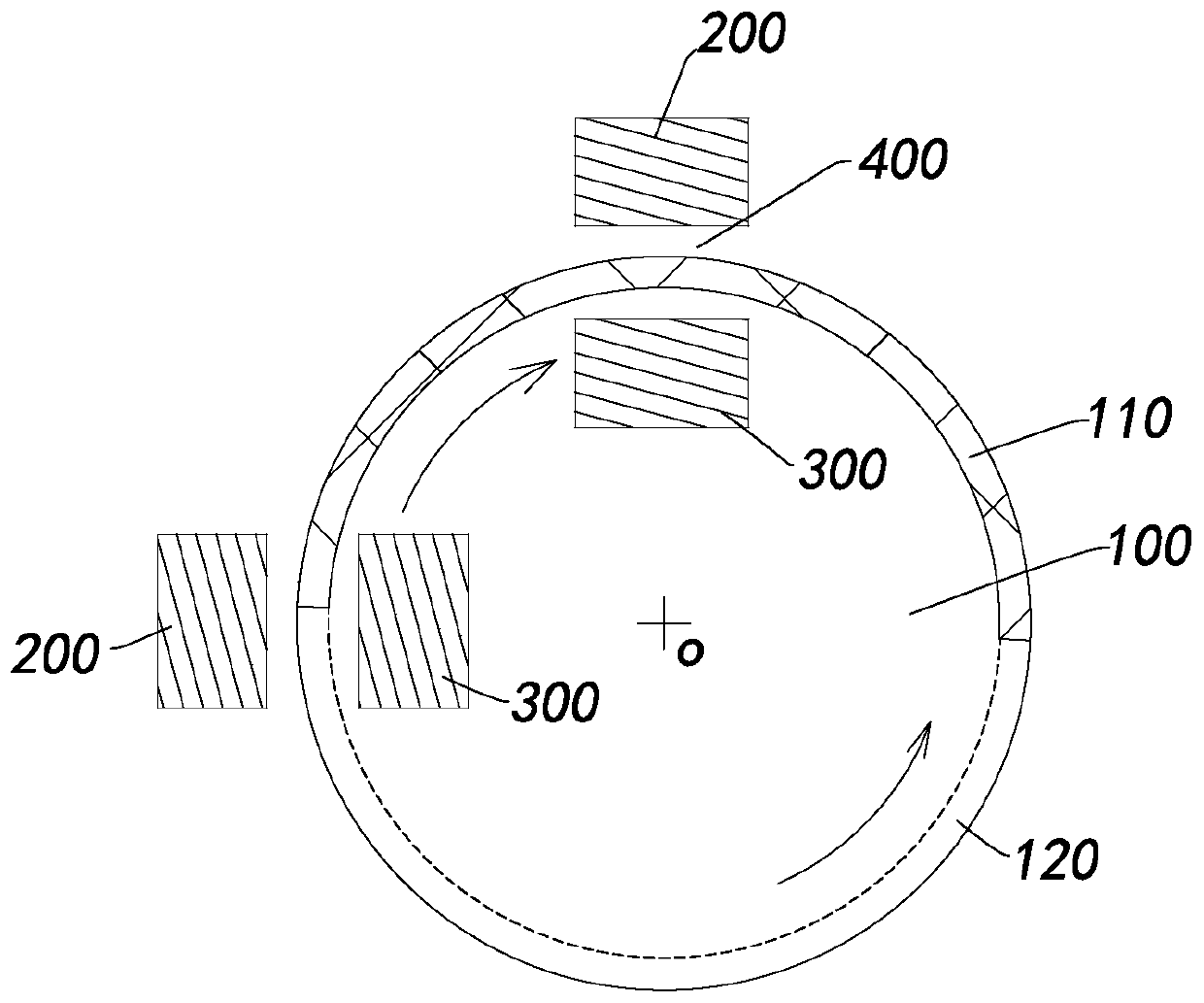
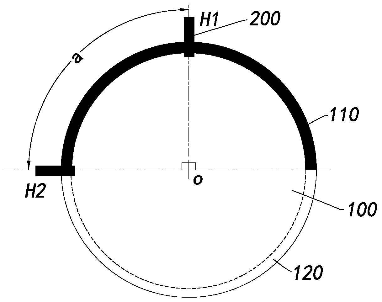
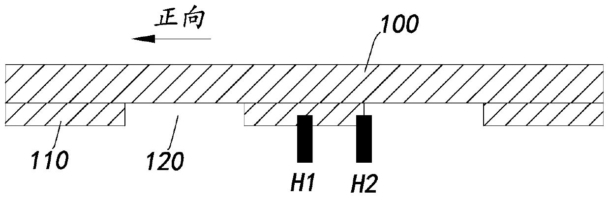
[0052] The photoelectric sampling device of the meter proposed by the present invention includes a light emitter; and a light receiver, the light receiver is arranged opposite to the light emitter and forms a light-irradiating area between the two; and, by the meter The base of the watch drives a rotating turntable, and the turntable is provided with a light-shielding part and a light-transmitting part, and the rotating motion of the turntable makes the light-shielding part and the light-transmitting part alternately pass through the light incident area. Sampling through-beam optical signal sampling solves the problem that light is easily interfered by external light in reflective optical signal sampling, reduces the difficulty of sampling signal identification, and requires the production process and assembly requirements of product parts.

[0053] The technical solutions of the embodiments of the present invention will be explained and described below in conjunction with the ...


PUM


Abstract

The invention discloses a meter and a photoelectric sampling device and a photoelectric sampling method of the meter, which belong to the technical field of flow measurement, and solve the problem oflight interference caused by the fact that an existing meter adopts reflection type optical signal sampling. The photoelectric sampling device of the meter comprises a light emitter, a light receiverand a rotary disc, wherein the light receiver and the light emitter are oppositely arranged, and a light correlation region is formed between the light receiver and the light emitter; and the rotary disc is driven by means of a base meter of the meter to rotate, a shading part and a light-transmitting part are arranged on the rotary disc, and the shading part and the light-transmitting part alternately pass through the light correlation region through the rotating motion of the rotary disc. According to the photoelectric sampling device and the photoelectric sampling method, correlation optical signal sampling is carried out, the problem that light is easily interfered by external light in reflection-type optical signal sampling is solved, the identification difficulty of sampled signals is reduced, and the manufacturing process requirement and the assembly requirement of product parts are reduced.

Description

【Technical field】 [0001] The invention relates to the technical field of flow metering, in particular to a photoelectric sampling device for a meter, a photoelectric sampling method and a meter. 【Background technique】 [0002] With the rapid development of smart meters, the industry has higher requirements for the accuracy and high performance of meter measurement. The sampling and metering methods of gas meters mainly include magnetic signal sampling and metering and optical signal sampling and metering. Although the magnetic signal sampling and metering technology is simple in design and low in power consumption, it is susceptible to magnetic field interference, resulting in a decrease in sampling accuracy and inaccurate measurement results. , the applicable occasions are limited. In contrast, although the optical signal sampling measurement is not interfered by the external magnetic field, it also has technical defects. Recognition, but high installation accuracy and co...

Claims


Application Information

Patent Timeline
Patent Type & Authority Applications(China)
IPC IPC(8): G01F1/56G01F1/66G01F15/06
CPCG01F1/56G01F1/661G01F1/662G01F15/063
Inventor 李忠园盛成龙
Owner GOLDCARD HIGH TECH
Why Eureka
Try Eureka