
Low-current test system

A test system and small current technology, applied in the direction of short-circuit test, current only measurement, current/voltage measurement, etc., can solve the problems that affect the stability of test results, cannot meet the needs of small current tests, etc., and achieve high test stability Effect

Inactive Publication Date: 2020-05-08
ZHUHAI BOJAY ELECTRONICS
View PDF5 Cites 0 Cited by
  • Summary
  • Abstract
  • Description
  • Claims
  • Application Information

AI Technical Summary

Problems solved by technology

However, due to the bias current and leakage current of the detection system itself, the traditional current test method cannot meet the needs of small current test, which seriously affects the stability of the test results.

Method used


Image

  • Low-current test system
  • Low-current test system
  • Low-current test system

Examples


Embodiment Construction

[0017] In order to enable those skilled in the art to better understand the present invention, the following will clearly and completely describe the technical solutions in the embodiments of the present invention. Obviously, the described embodiments are only a part of the present invention, rather than Full examples.

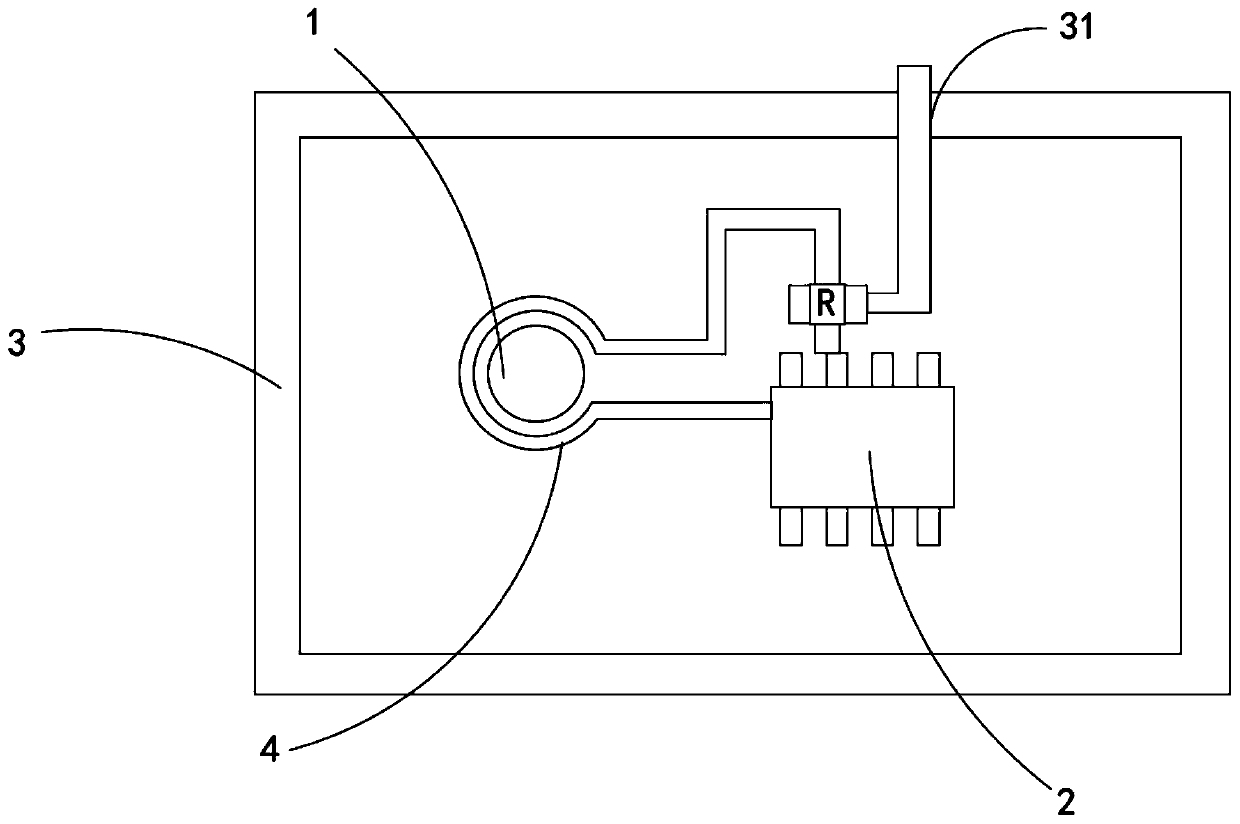
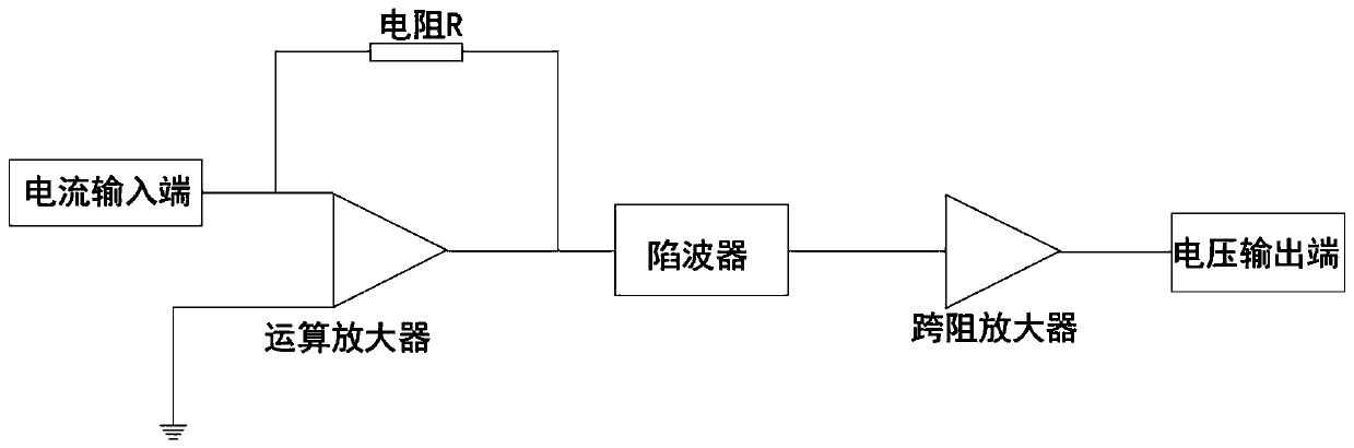
[0018] The embodiment of the present invention discloses a small current test system, such as figure 1 As shown, it includes a current input terminal, a resistor R, a resonant circuit, a current-voltage converter, and a voltage output terminal. The current input terminal is connected to the resonant circuit through the resistor R, and the resonant circuit is connected to the voltage output terminal through the current-voltage converter. .

[0019] optional, such as figure 1 As shown, the current-to-voltage converter is a transimpedance amplifier.

[0020] optional, such as figure 1 As shown, the resonant circuit is a 50Hz trap.

[0021] In particular, the...


PUM


Abstract

The invention provides a low-current test system, which comprises a current input end, a resistor R, a resonance circuit, a current-voltage converter and a voltage output end, wherein the current input end is connected with the resonance circuit by means of the resistor R, and the resonance circuit is connected with the voltage output end by means of the current-voltage converter. According to a traditional current testing method, bias current, leakage current and the like exist in a detection system, so that the requirement of low-current testing cannot be met, and the stability of a detection result is seriously influenced. The low-current test system adopts a circuit formed by combining the current input end, the resistor R, the resonance circuit, the current-to-voltage converter and the voltage output end, effectively achieves precise detection of low current, and has high test stability.

Description

technical field [0001] The invention relates to a current testing system, in particular to a small current testing system. Background technique [0002] With the development of microelectronic components, major manufacturers have become more and more stringent on the quality control of electronic components, especially the need to test extremely small leakage currents for TVS tubes and other products, and put forward relatively high requirements for test stability. requirements. However, due to the bias current and leakage current of the detection system itself, the traditional current test method cannot meet the needs of small current test, which seriously affects the stability of the test results. Contents of the invention [0003] The invention provides a small current testing system to realize accurate detection of small current. [0004] The present invention provides a small current test system, which includes a current input terminal, a resistor R, a resonant circ...

Claims


Application Information

Patent Timeline
IPC IPC(8): G01R19/00G01R31/52
CPCG01R19/0092
Inventor 赵伟林梁树彬杨进权
Owner ZHUHAI BOJAY ELECTRONICS
Features
  • Generate Ideas
  • Intellectual Property
  • Life Sciences
  • Materials
  • Tech Scout
  • Unparalleled Data Quality
  • Higher Quality Content
  • 60% Fewer Hallucinations
Learn More