High-precision extinction ratio test method and system

A test method and technology of extinction ratio, applied in the field of optical communication, can solve the problem of test accuracy, poor working stability, large fluctuation of the transconductance value of PIN photodiode responsivity, and inability to measure the true value of the extinction ratio of the optical module under test, etc. problem, to achieve the effect of high-precision measurement and stable temperature characteristics

Inactive Publication Date: 2014-12-24
NINGBO MOSHI OPTOELECTRONICS TECH
View PDF7 Cites 9 Cited by
  • Summary
  • Abstract
  • Description
  • Claims
  • Application Information

AI Technical Summary

Problems solved by technology

[0008] The extinction ratio test system still uses the method of directly measuring the average optical power when the optical signals are "1" and "0" respectively, and then calculating the extinction ratio. Although it is theoretically possible, in practical applications, due to the PIN type photoelectric The responsivity of the diode and the transconductance of the transimpedance amplifier fluctuate greatly due to the influence of the ambient temperature, resulting in extremely poor test accuracy and working stability. At the same time, the signal detector is limited by the bandwidth of the device and can only work at a specific rate, which cannot be realized. High-speed optical signal extinction ratio measurement in a wide rate range; in addition, limited by the linear working area of ​​the transimpedance amplifier, when the input signal exceeds its saturation operating point, the output signal will be distorted, making it impossible to measure the extinction of the optical module under test than the true value

Method used


Image

  • High-precision extinction ratio test method and system
  • High-precision extinction ratio test method and system
  • High-precision extinction ratio test method and system

Examples


Embodiment Construction

[0057] In order to make the purpose, technical solution and advantages of the present application clearer, the present application will be further described in detail below in conjunction with the accompanying drawings and specific embodiments.

[0058] For simplicity, some technical features known to those skilled in the art are omitted from the following description.

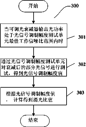
[0059] refer to image 3 , image 3 Shown is a flowchart of an embodiment 300 of the high-precision extinction ratio testing method of the present invention. Method 300 includes steps 301 to 303 .

[0060] In step 301, the optical signal is attenuated by the adjustable optical attenuator until its output optical power is within the optimal working signal-to-noise ratio range of the optical signal modulation amplitude test unit; refer to Figure 4 , Figure 4 It is a flow chart of an embodiment of a method 400 for attenuating part of the optical signal to the range of the best working signal-to-noise ratio ...


PUM


Abstract

The invention discloses a high-precision extinction ratio test method and system. The method includes the steps that when light signals are attenuated to be within a best work signal-to-noise ratio range of a light signal modulation amplitude test unit, and a part of the attenuated light signals are tested through the light signal modulation amplitude test unit to obtain a light signal modulation amplitude value; the extinction ratio is calculated according to the light signal modulation amplitude value. A method based on high-speed radio frequency signal peak-to-peak value detection is adopted, the extinction ratio of the detected light signals is converted into low-frequency voltage signals, and the aim of measuring the high-speed light signal extinction ratio at high precision is achieved on various signal code pattern and modulation format conditions in a wide signal speed range; meanwhile, the system greatly extends the dynamic range of the light signals capable of being tested, and testing precision, consistence of repeated tests and work stability of a test device are improved.

Description

technical field [0001] The invention relates to the field of optical communication, in particular to a high-precision extinction ratio testing method and system. Background technique [0002] In the field of optical communications, the extinction ratio of optical signals is an important technical indicator, especially in the R&D, testing, and manufacturing of optical modules and optical devices. The extinction ratio of optical signals output by optical transmitters is an important parameter that must be tested; figure 1 A system connection diagram commonly used in optical module extinction ratio testing is provided; according to the calculation formula of extinction ratio: It can be seen that if the extinction ratio of the optical signal needs to be tested, the average optical power "P0" when the modulation signal is "0" and the average optical power "P1" when the modulation signal is "1" must be measured. [0003] With the improvement of optical fiber communication networ...

Claims


Application Information

Patent Timeline
Patent Type & Authority Applications(China)
IPC IPC(8): H04B10/079
Inventor 屠澄轶白晓明易少宾陈仕隆杨雷赵泽东殷飞吕坤
Owner NINGBO MOSHI OPTOELECTRONICS TECH
Why Eureka
Try Eureka