
Large-scale parallel mesh generation system and method for finite element analysis

A technique of grid division and finite element, applied in the field of finite element analysis

Inactive Publication Date: 2020-05-08
UNIV OF SCI & TECH BEIJING
View PDF11 Cites 5 Cited by
  • Summary
  • Abstract
  • Description
  • Claims
  • Application Information

AI Technical Summary

Problems solved by technology

[0005] The technical problem to be solved by the present invention is to provide a large-scale parallel grid division system and method for finite element analysis, so as to solve the problem that there is currently no available solution for large-scale parallel grid division of the reactor core model and efficient large-scale grid division. Finite element analysis solves problems that fit well together

Method used


Image

  • Large-scale parallel mesh generation system and method for finite element analysis
  • Large-scale parallel mesh generation system and method for finite element analysis
  • Large-scale parallel mesh generation system and method for finite element analysis

Examples


no. 1 example

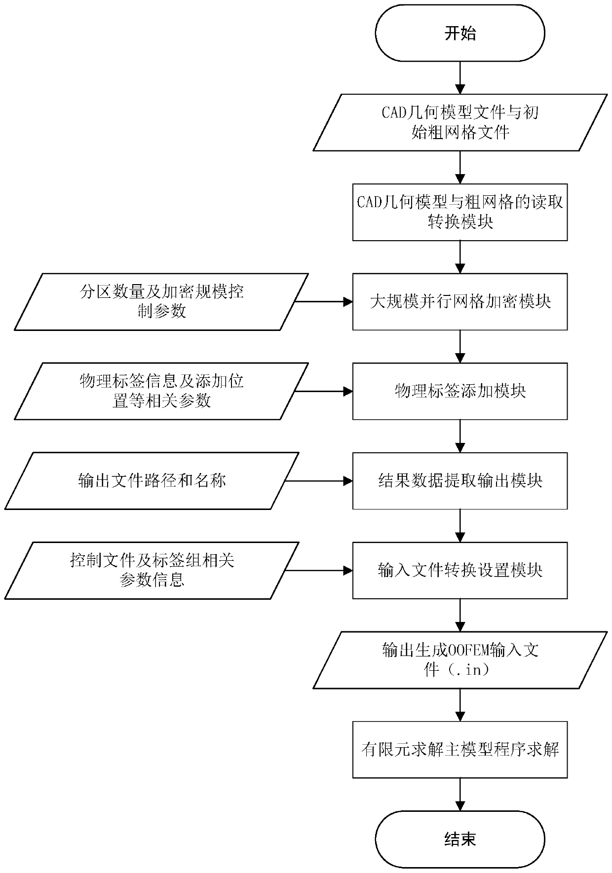
[0081] see Figure 1 to Figure 6 , the present embodiment provides a large-scale parallel meshing system for finite element analysis, which mainly includes five functional modules, which are used to read and convert CAD geometric model files and initial coarse meshes, and realize large-scale parallel mesh encryption , and apply the large-scale parallel grid division result data to the finite element solution main model program. In actual use, these five functional modules are connected in series to form a complete preprocessing part, and each module program is called sequentially to finally realize the parallel division. The obtained grid result data is submitted to the finite element solution main model program for analysis and calculation. The specific process is as follows: figure 1 shown.

[0082] Specifically, the five functional modules of the large-scale parallel meshing system for finite element analysis are: the CAD geometric model and coarse mesh used to generate th...

no. 2 example

[0104] This embodiment provides a large-scale parallel mesh division method for finite element analysis, and the large-scale parallel mesh division method for finite element analysis includes the following steps:

[0105] S1, generating a CAD geometric model file and a coarse grid file in a preset format of the nuclear reactor core;

[0106] Specifically, in this embodiment, the above steps include the following process:

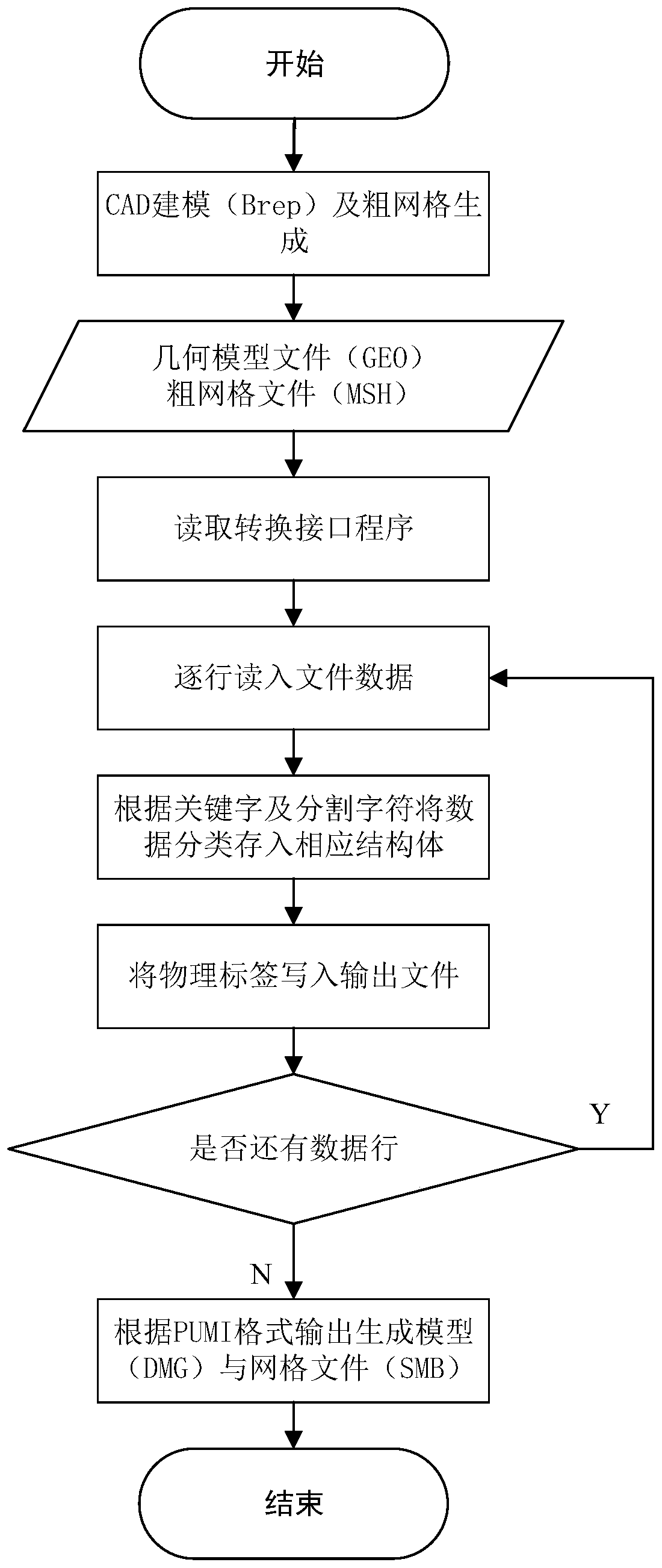
[0107] S11, adopt boundary representation method (Brep) to carry out CAD modeling to reactor core structure, and use GMSH to carry out initial coarse grid division, obtain CAD model file and initial coarse grid file;

[0108] S12, convert the obtained CAD model file and the initial coarse grid file into a custom format that PUMI can use through the format conversion interface program, and input it to PUMI for subsequent operations;

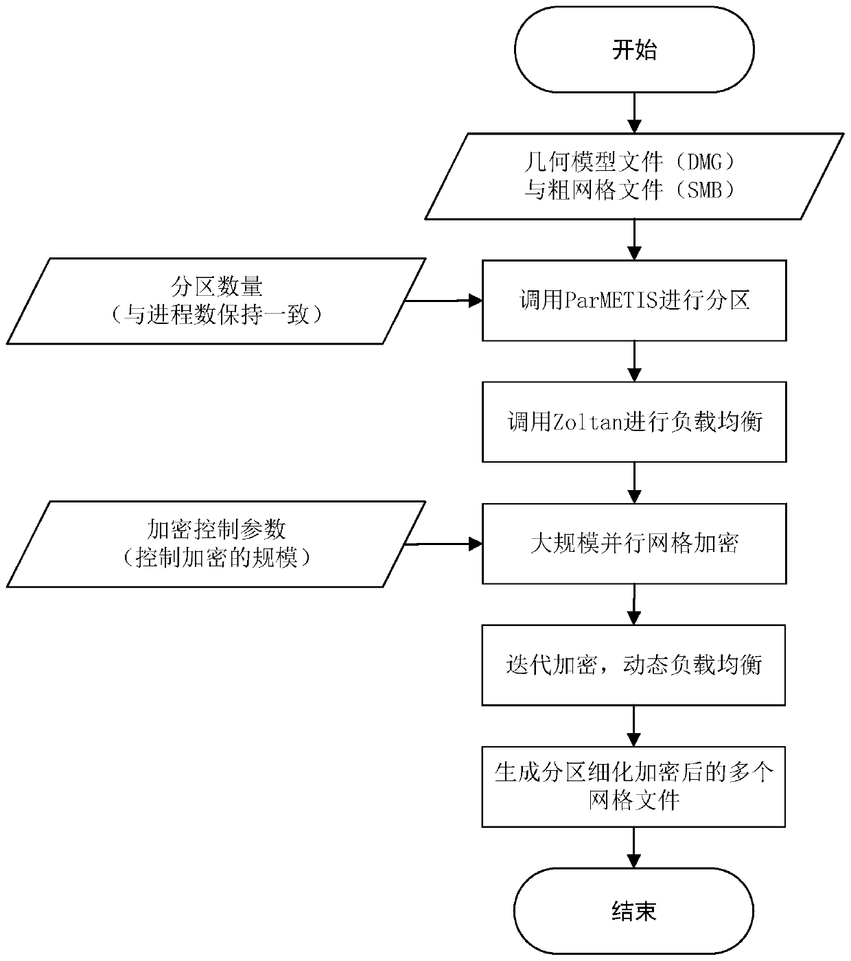
[0109] S2, based on the CAD geometric model file and the coarse grid file, perform grid encryption on the coarse grid file; ...


PUM


Abstract

The invention provides a large-scale parallel grid division system and method for finite element analysis, and the system comprises a CAD geometric model and coarse grid reading and conversion modulewhich is used for generating a CAD geometric model file and a coarse grid file in a preset format; a large-scale parallel grid encryption module which is used for carrying out grid encryption on the coarse grid file; a grid physical label adding module which is used for adding a physical label to the encrypted grid file; a grid result extraction output module which is used for extracting corresponding grid data from the grid file added with the physical label; and an input file conversion setting module which is used for combining the analysis parameters and the grid result file and convertingthe analysis parameters and the grid result file into an input file in a format required by finite element solving software. The reactor core structure can be modeled, large-scale parallel mesh generation can be completed, and then mesh result data is applied to finite element solving software, so that the purpose of high-precision and high-efficiency analog calculation of reactor core structuremechanics is finally achieved.

Description

technical field [0001] The invention relates to the technical field of finite element analysis, in particular to a large-scale parallel grid division system and method for finite element analysis. Background technique [0002] The bending deformation of the reactor core assembly and the flow-induced vibration of the fuel rods under the joint action of high temperature, radiation, fluid, compaction force and other factors lead to cladding wear of the reactor core assembly, difficulty in loading and unloading, component damage and fatigue. main cause of injury. It is of great significance to study the deformation of core components and the analysis of flow-induced vibration to ensure the safe operation of the reactor. Due to the particularity of the arrangement of components in the core, the temperature, radiation, and flow fields are very complicated, and it is quite difficult to analyze them using theoretical analysis methods. In actual work, numerical methods are generall...

Claims


Application Information

Patent Timeline
IPC IPC(8): G06F30/23G06F21/60G06F16/11G06F16/16
CPCG06F21/602G06F2221/2107G06F16/116G06F16/16
Inventor 岑鑫邢龙岳蒋章程朱迎王昭顺胡长军杨文冯仰德高付海高岳
Owner UNIV OF SCI & TECH BEIJING
Learn More