Fiber laser power control method and device

A fiber laser and power control technology, which is applied to lasers, laser components, phonon exciters, etc., can solve problems such as inaccurate adjustment, and achieve the effects of precise adjustment, high adjustment accuracy, and accurate output power

Inactive Publication Date: 2020-05-08
武汉思创精密激光科技有限公司
View PDF9 Cites 0 Cited by
  • Summary
  • Abstract
  • Description
  • Claims
  • Application Information

AI Technical Summary

Problems solved by technology

[0004] The purpose of the present invention is to solve the shortcomings of inaccurate adjustment in the prior art, and propose a fiber laser power control method and device

Method used


Image

  • Fiber laser power control method and device
  • Fiber laser power control method and device
  • Fiber laser power control method and device

Examples


Embodiment 1

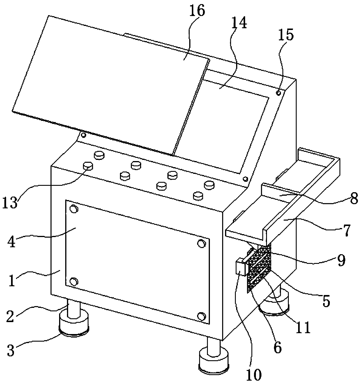
[0026] refer to Figure 1-4 , a fiber laser power control device, comprising a housing 1, the bottom end of the housing 1 is connected with several support mechanisms, the function of the support mechanism is to support the housing 1, the housing 1 is fixedly connected with an access panel 4, the access panel The function of 4 is to facilitate the maintenance of the internal mechanism of the shell 1. The control component is connected to the shell 1. The control component includes a processor, and the signal of the processor is connected to a conversion module. The function of the conversion module is to convert electrical signals into digital signals, convert The module signal is connected with a receiving module, the function of the receiving module is to receive the data transmitted by the fiber laser, the processor signal is connected with an adjustment module, the function of the adjustment module is to adjust the output power of the fiber laser, the processor signal is co...

Embodiment 2

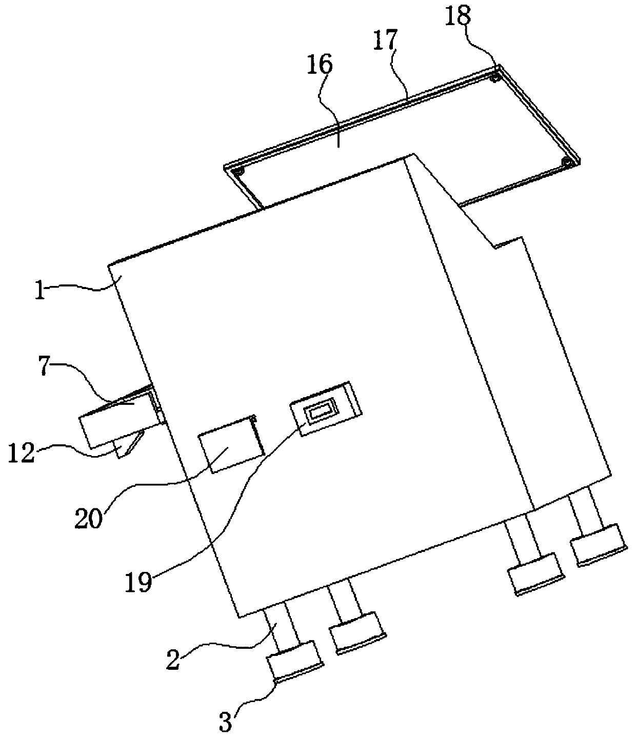
[0034] refer to Figure 1-2 , as another preferred embodiment of the present invention, the difference from Embodiment 1 is that the support mechanism includes a support foot 2, the support foot 2 is connected to the housing 1, and the bottom end of the support foot 2 is fixedly connected with an anti-slip pad 3, and the bottom of the anti-slip pad 3 The effect is to increase the frictional force between the support foot 2 and the ground, and the anti-skid pad 3 is a rubber pad.

Embodiment 3

[0036] refer to Figure 1-3 , as another preferred embodiment of the present invention, the difference from Embodiment 1 is that the housing 1 is provided with a cooling hole 5, the cooling hole 5 is fixedly connected with a dust-proof net 6, and the upper end of the housing 1 is connected with a fixing mechanism, The effect of fixing mechanism is to fix transparent plate 16, and fixing mechanism is connected with transparent plate 16, and the effect of transparent plate 16 is to protect display screen 14, and transparent plate 16 is a glass plate, and sealing ring 17 is fixedly connected on transparent plate 16, and sealing ring 17 The function is to seal the gap between the transparent plate 16 and the housing 1, one side of the sealing ring 17 squeezes the housing 1, the fixing mechanism includes several connecting seats 15, the connecting seats 15 are fixed on the housing 1, and the transparent plate 16 is fixedly connected with several connectors 18, and the connectors 18...


PUM


Abstract

The invention relates to the technical field of fiber lasers, and particularly to a fiber laser power control device. The fiber laser power control device comprises a shell, the bottom end of the shell is connected with a plurality of supporting mechanisms. The shell is fixedly connected with an overhauling plate, and a control assembly is connected into the shell. The upper end of the shell is connected with a display screen, the upper end of the shell is connected with an adjusting button, and one side of the shell is rotationally connected with a supporting plate. The upper end of the supporting plate is fixedly connected with a partition plate. The bottom end of the supporting plate is rotationally connected with an inserting rod. A fixing block is fixedly connected to the shell and located below the supporting plate, a through hole is formed in the upper end of the fixing block and matched with the inserting rod, elastic blocks are fixedly connected to the two sides of the lower surface of the supporting plate, a plug is fixedly connected to one side of the shell, a sliding groove is formed in the plug, and a baffle is connected to the sliding groove in a sliding mode. The invention also provides a fiber laser power control method. According to the invention, the adjustment precision is higher, and the output power of the fiber laser is adjusted accurately.

Description

technical field [0001] The invention relates to the technical field of fiber lasers, in particular to a method and device for controlling the power of a fiber laser. Background technique [0002] For an ideal fiber laser, its actual output power should be proportional to the theoretical set power, but due to the influence of individual differences in fiber laser components, temperature and other factors, at the same set power, The actual output power of different fiber lasers will be different. [0003] The existing control device needs some reference materials when adjusting the output power of the fiber laser, but because the adjustment device lacks a shelf, the reference materials cannot be placed, which is not conducive to adjusting the output power of the fiber laser, resulting in inaccurate adjustment . Contents of the invention [0004] The purpose of the present invention is to solve the shortcomings of inaccurate adjustment in the prior art, and propose a fiber ...

Claims


Application Information

Patent Timeline
Patent Type & Authority Applications(China)
IPC IPC(8): H01S3/067H01S3/00
CPCH01S3/0007H01S3/067H01S3/06704
Inventor 徐港李威陈科帆黄灿丁中华
Owner 武汉思创精密激光科技有限公司
Why Eureka
Try Eureka