Forced lithium battery charger

A lithium battery and charger technology, applied in battery circuit devices, current collectors, charging/discharging current/voltage regulation, etc., can solve the problems of unsatisfactory charging, slow charging speed, etc., to increase charging speed, reduce charging time, improve The effect of charge saturation

Inactive Publication Date: 2020-05-08
钟建华
View PDF0 Cites 0 Cited by
  • Summary
  • Abstract
  • Description
  • Claims
  • Application Information

AI Technical Summary

Problems solved by technology

[0003] Aiming at the above-mentioned defects existing in the prior art, the present invention proposes a forced lithium battery charger, which solves the problem of slow charging speed and unsatisfactory charging by setting up two direction-changing oscillating electric fields in the direction of the charging pole with an auxiliary electric field and perpendicular to the charging pole. question

Method used


Image

  • Forced lithium battery charger
  • Forced lithium battery charger
  • Forced lithium battery charger

Examples


Embodiment 1

[0021] The following will clearly and completely describe the technical solutions in the embodiments of the present invention with reference to the accompanying drawings in the embodiments of the present invention. Obviously, the described embodiments are only some, not all, embodiments of the present invention. Based on the embodiments of the present invention, all other embodiments obtained by persons of ordinary skill in the art without making creative efforts belong to the protection scope of the present invention.

[0022] Example 1:

[0023] Existing lithium battery chargers use simple positive and negative poles to charge the lithium battery 5. Due to battery resistance and other reasons, the charging speed is slow, and the congestion at the negative pole makes the charging speed slow and the charging capacity is not enough.

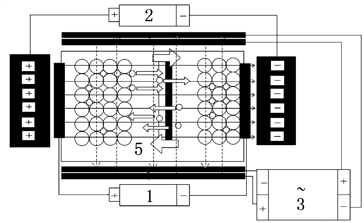
[0024] The present invention reduces the resistance of the original charging electrode 1 ( figure 1 ), to speed up the charging speed and reduce...

Embodiment 2

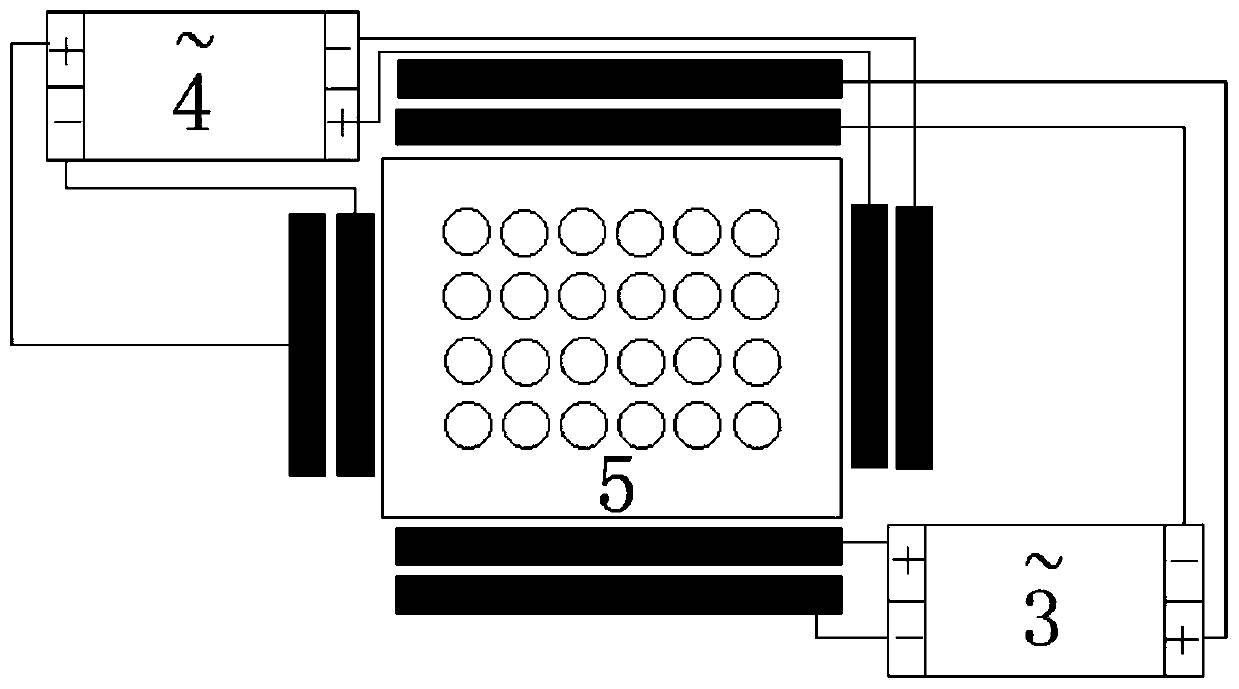
[0031] In the existing lithium battery charger, the lithium battery 5 is located between the original charging poles 1, the original charging pole 1 applies a common charging electric field 1-1 to the lithium battery 5, and the two sides of the polymer diaphragm in the middle of the lithium battery 5 are respectively provided with The positive electrode material and the negative electrode material, the positive plate of the original charging electrode 1 is arranged on the outside of the positive electrode material of the battery, the negative electrode plate of the original charging electrode 1 is arranged on the outside of the negative electrode material of the battery, when the original charging electrode 1 is energized, the lithium battery 5 is charged, and the positive electrode material ( LiCoO 2 ) Lithium ions in the negative electrode material slowly pass through the polymer membrane to form a charging process; on the contrary, lithium ions in the negative electrode mate...


PUM


Abstract

The invention relates to a forced lithium battery charger, and belongs to the technical field of lithium battery charging devices. According to the forced charging electrode disclosed by the invention, a same-direction forced charging electric field is arranged in the direction of the original charging electrode, so lithium ions in the lithium battery obtain a larger charging potential, and the lithium ions go deep into the deep part of the negative electrode; a vertical charging electrode is a vertical turning oscillation electric field arranged in the vertical direction of the original charging electrode, so lithium ions in the lithium battery continuously vibrate up and down along the advancing direction to reduce and avoid congestion; a horizontal charging electrode is a horizontal turning oscillation electric field arranged in the vertical direction of the original charging electrode, so lithium ions in the lithium battery continuously vibrate left and right in the advancing direction, and congestion is reduced and avoided; under the action of the forced charging electric field, the vertical turning oscillation electric field and the horizontal turning oscillation electric field, lithium ions in the lithium battery are always in three-dimensional motion. The charging speed can be improved, the charging time is shortened, and the charging saturation is improved.

Description

technical field [0001] The invention relates to a forced lithium battery charger, which belongs to the technical field of lithium battery charging devices. Background technique [0002] Existing lithium batteries are respectively provided with positive electrode materials and negative electrode materials on both sides of the polymer diaphragm. Lithium ions in the positive electrode material slowly enter the negative electrode material through the polymer diaphragm to form a charging process; however, due to the insufficient electromotive force provided by the original charging electrode, The depth of lithium ions entering the negative electrode material through the polymer separator is limited, and during the forward movement of lithium ions, they are hindered by a large resistance, resulting in slow charging and insufficient charging. Contents of the invention [0003] Aiming at the above-mentioned defects existing in the prior art, the present invention proposes a forced...

Claims


Application Information

Patent Timeline
IPC IPC(8): H02J7/00
CPCH02J7/007
Inventor 钟建华
Owner 钟建华
Why Eureka
Try Eureka