High-pressure-bearing combined type steel structure and welding method

A combined, steel structure technology, applied in welding equipment, building construction, construction, etc., can solve the problems of troublesome installation and use, inconvenient height, etc., and achieve the effects of strong practicability, convenient installation, and wide application range

Active Publication Date: 2020-05-12
广东华域重工有限公司
View PDF7 Cites 3 Cited by
  • Summary
  • Abstract
  • Description
  • Claims
  • Application Information

AI Technical Summary

Problems solved by technology

[0004] In order to overcome the above-mentioned technical problems, the object of the present invention is to provide a high pressure-bearing combined steel structure and welding method. By rotating the rocker and driving the screw to rotate, the screw drives the threaded sleeve to move relatively or away from each other, and then the threaded sleeve Drive two movable rods to move, and then drive the rocker arm to slide in the chute 2 and chute 1 through the movable rod 2, push the adjustment plate up and down, and then drive the mounting seat to rise and fall; through the setting of the movable mechanism, it is convenient to drive and adjust the mounting seat. High, easy to install, easy to use, and strong practicability, which solves the problem that the existing steel structure is not easy to adjust its height, which makes its installation and use more troublesome;

Method used


Image

  • High-pressure-bearing combined type steel structure and welding method
  • High-pressure-bearing combined type steel structure and welding method
  • High-pressure-bearing combined type steel structure and welding method

Examples


Embodiment Construction

[0039] The following will clearly and completely describe the technical solutions in the embodiments of the present invention with reference to the accompanying drawings in the embodiments of the present invention. Obviously, the described embodiments are only some, not all, embodiments of the present invention. Based on the embodiments of the present invention, all other embodiments obtained by persons of ordinary skill in the art without creative efforts fall within the protection scope of the present invention.

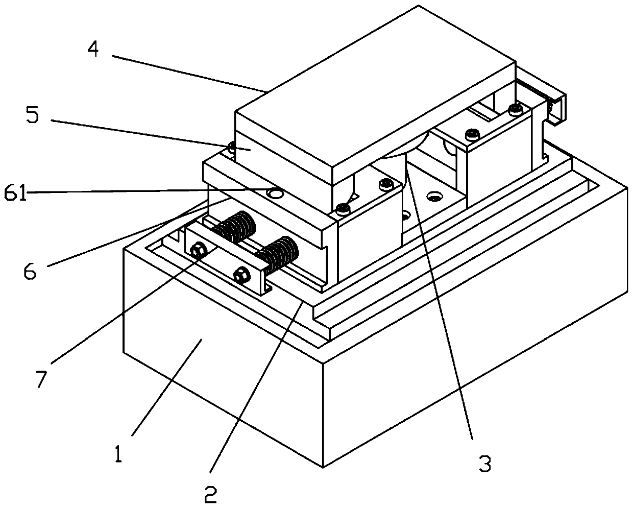
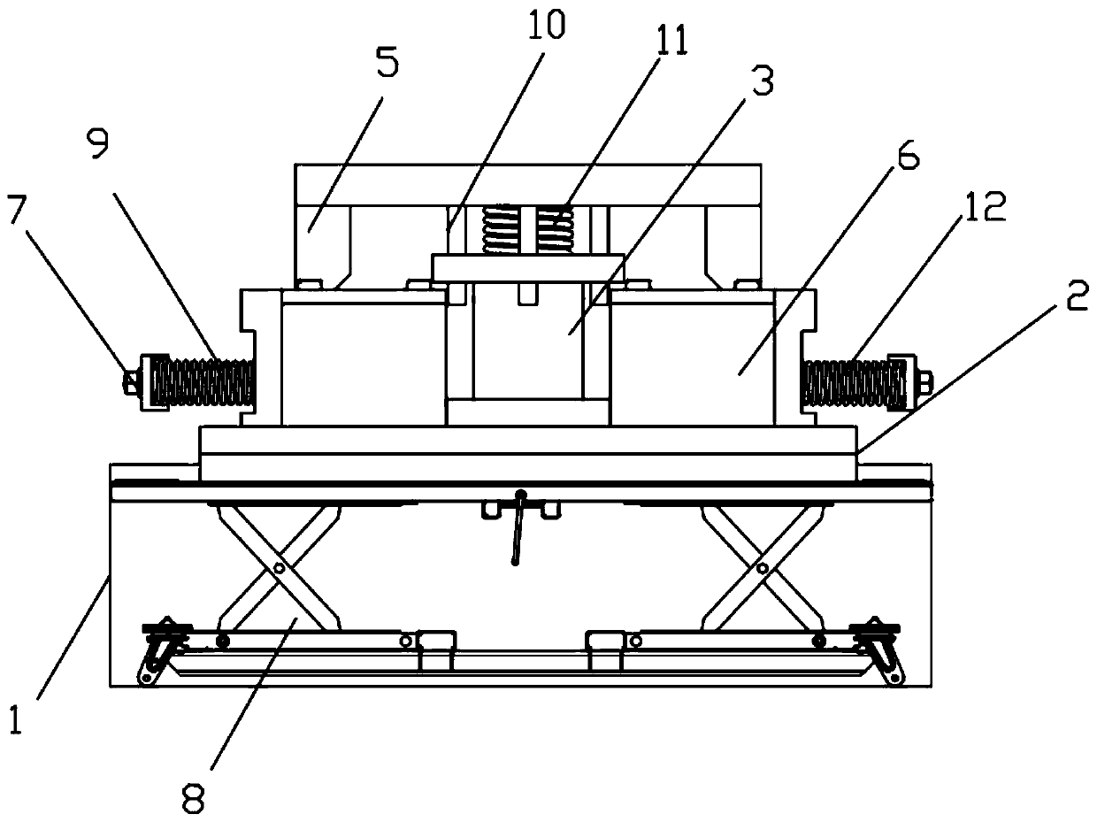
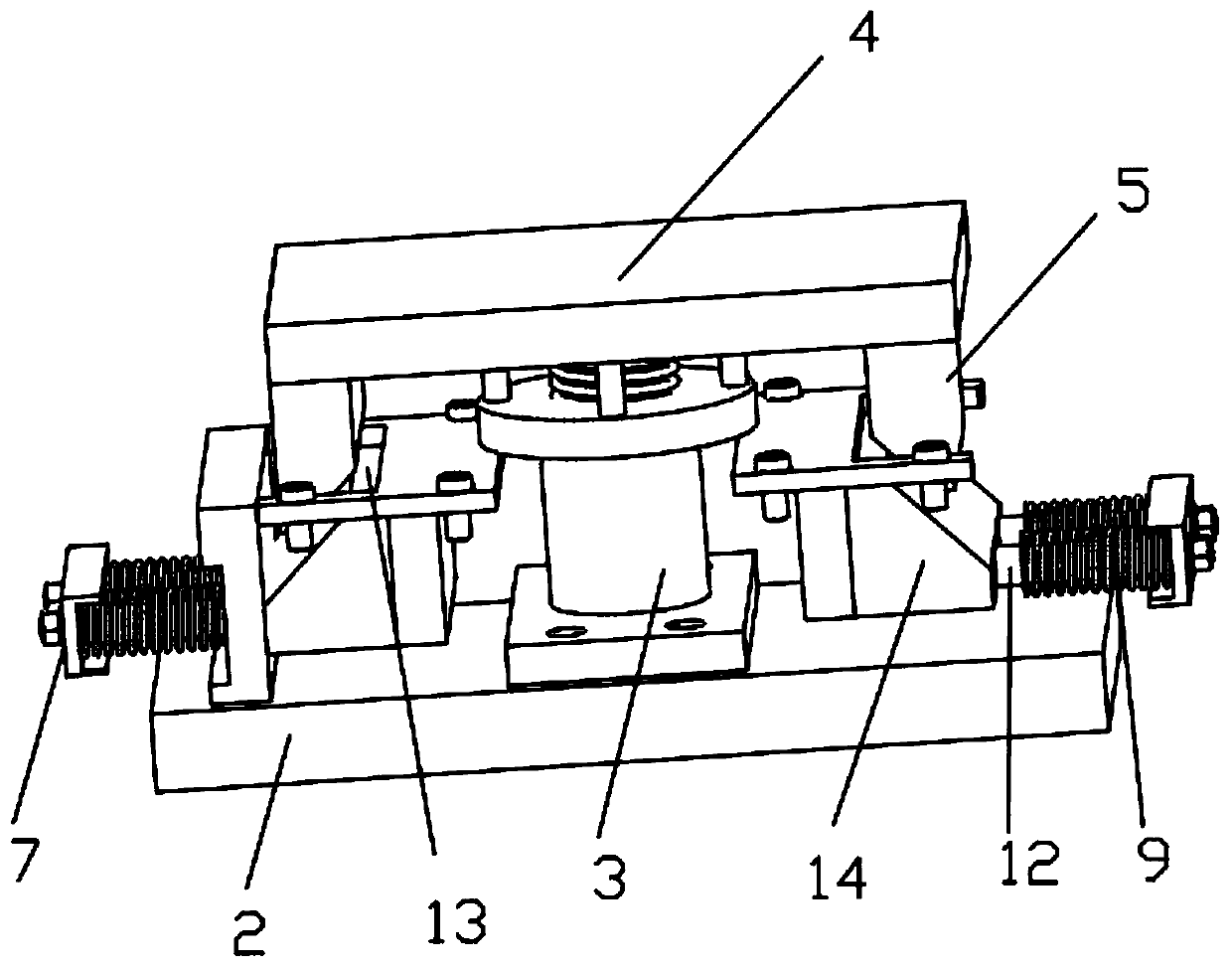
[0040] see Figure 1-7 As shown, a high pressure-bearing combined steel structure includes a base 1, a mounting seat 2, a support column 3, and a top plate 4. The base 1 is a groove-shaped structure, and a movable mechanism 8 is fixedly installed inside the base 1. , the top of the movable mechanism 8 is fixedly installed with a mounting base 2, and the two ends of the top of the mounting base 2 are symmetrically equipped with a box body 6, and the inside of the bo...


PUM


Abstract

The invention discloses a high-pressure-bearing combined type steel structure and a welding method. The high-pressure-bearing combined type steel structure comprises a base, a mounting base, a supporting column and a top plate, wherein the base is of a groove-shaped structure, a movable mechanism is fixedly mounted in the base, the mounting base is fixedly mounted at the top of the movable mechanism, and box bodies are symmetrically mounted at the two ends of the top of the mounting base. According to the structure, the top plate descends due to pressure, second springs are compressed, telescopic rods compress lifting springs, first wedge blocks descend to be in contact with second wedge blocks, the second springs and the lifting springs continue to be compressed, the top plate continues to descend, the first wedge blocks and the second wedge blocks cooperate with each other, then the first wedge blocks push the second wedge blocks to slide horizontally, the second wedge blocks drive limiting blocks to move through fourth movable rods, and the first springs are compressed. Under the combined action of the lifting springs, the first springs and the second springs, step-by-step buffering is carried out, so that the pressure-bearing performance of the steel structure is improved.

Description

technical field [0001] The invention relates to the technical field of steel structures, in particular to a high pressure-bearing combined steel structure and a welding method. Background technique [0002] Steel structure is a structure composed of steel materials, which is one of the main types of building structures. The structure is mainly composed of beam steel, steel column, steel truss and other components made of section steel and steel plate, and adopts rust removal and antirust processes such as silanization, pure manganese phosphating, washing and drying, and galvanizing. The components or components are usually connected by welds, bolts or rivets. Because of its light weight and easy construction, it is widely used in large factories, stadiums, super high-rises and other fields. [0003] Patent No. CN208668631U discloses a high pressure-bearing combined steel structure. The steel structure uses a fixed frame to strengthen the pressure-bearing performance and ef...

Claims


Application Information

Patent Timeline
IPC IPC(8): E04B1/00E04B1/343E04B1/38B23K31/02
CPCB23K31/02E04B1/00E04B1/343E04B1/38
Inventor 易新河
Owner 广东华域重工有限公司
Why Eureka
Try Eureka