Supercharge Your Innovation With Domain-Expert AI Agents!

egr mixer and engine

A mixer and engine technology, applied in the direction of machines/engines, engine components, mechanical equipment, etc., can solve the problems of poor gas mixing effect, low circumferential EGR rate, low EGR rate, etc., and achieve the effect of improving the mixing effect.

Active Publication Date: 2020-08-21
WEICHAI POWER CO LTD
View PDF6 Cites 0 Cited by
  • Summary
  • Abstract
  • Description
  • Claims
  • Application Information

AI Technical Summary

Problems solved by technology

The surround-type EGR mixer has a high EGR rate on the circumferential wall and a low EGR rate in the core area of ​​the axis; while the plug-in EGR mixer has a high EGR rate at the core and a low EGR rate in the circumferential direction, which makes the gas mixing effect when entering the cylinder poor

Method used


Image

  • egr mixer and engine
  • egr mixer and engine
  • egr mixer and engine

Examples


Embodiment Construction

[0033] The core of the present invention is to provide an EGR mixer whose mixing effect is improved. Another core of the present invention is to provide an engine including the above-mentioned EGR mixer.

[0034] In order to enable those skilled in the art to better understand the technical solutions of the present invention, the present invention will be further described in detail below in conjunction with the accompanying drawings and embodiments.

[0035] Please refer to Figure 1 to Figure 9 .

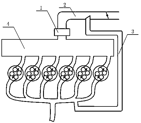
[0036] In a specific embodiment, the EGR mixer provided by the specific embodiment of the present invention includes an intake manifold 2, an EGR introduction pipe 3 and a second mixer 1, and the EGR introduction pipe 3 is connected with the intake manifold 2 to form the first mixer Yes, the second mixer 1 is installed on the intake manifold 2 and is located downstream of the first mixer.

[0037] When the engine is working, the exhaust gas enters the intake manifold 2 through ...


PUM


Abstract

The invention discloses an EGR mixer and an engine. The EGR mixer comprises an intake manifold, an EGR lead-in pipe and a second mixer, wherein the EGR lead-in pipe is connected with the intake manifold to form a first mixer, and the second mixer is arranged on the intake manifold and is positioned at the downstream position of the first mixer. When the engine works, exhaust gas enters the intakemanifold through the EGR lead-in pipe, and air enters through an air inlet of the intake manifold and is mixed once at the first mixer. The mixed gas flows through the second mixer for secondary mixing, and the gas enters an air cylinder after mixing. In the EGR mixer, the gas is mixed once through the first mixer, and the mixed gas is mixed twice in the intake manifold, so the gas is mixed twicebefore entering the air cylinder. Thus the mixing effect of the EGR mixer is improved.

Description

technical field [0001] The invention relates to the technical field of engine air intake mixing, in particular to an EGR mixer. The invention also relates to an engine comprising the EGR mixer described above. Background technique [0002] The EGR mixer is a technology that separates part of the exhaust gas after combustion in the internal combustion engine and introduces it into the intake side for re-combustion. The main purpose is to reduce nitrogen oxides in the exhaust gas and improve fuel consumption when sharing part of the load. [0003] The traditional EGR mixer includes an intake manifold and an EGR introduction pipe connected to the intake manifold. A mixer is formed at the connection between the EGR introduction pipe and the intake manifold to realize the mixing of exhaust gas and air. The mixed gas enters the cylinder through the outlet of the intake manifold. [0004] Traditional mixers are divided into surround-type EGR mixers, and the other type is plug-in ...

Claims


Application Information

Patent Timeline
Patent Type & Authority Patents(China)
IPC IPC(8): F02M26/19
CPCF02M26/19
Inventor 李卫李云刚潘洁袁志玲史孝华高用量
Owner WEICHAI POWER CO LTD
Features
  • R&D
  • Intellectual Property
  • Life Sciences
  • Materials
  • Tech Scout
  • Unparalleled Data Quality
  • Higher Quality Content
  • 60% Fewer Hallucinations
Learn More