
Hydroelectric power generation tower utilizing vertical potential energy

A vertical and potential energy technology, applied in the direction of engines, machines/engines, mechanical equipment, etc., can solve problems such as inability to improve power supply efficiency and consume large water resources

Inactive Publication Date: 2020-05-12
杨健成
View PDF17 Cites 1 Cited by
  • Summary
  • Abstract
  • Description
  • Claims
  • Application Information

AI Technical Summary

Problems solved by technology

[0002] The common hydroelectric power generation in public construction basically uses the way of flood discharge from reservoirs to generate power. In order to improve its power generation efficiency, it mostly relies on the impact force achieved by the water level drop (that is, the kinetic energy generated by the water level difference) to generate electricity. As energy, it drives the water flange generator to generate electricity. Therefore, this kind of hydroelectric power generation that uses reservoir flood discharge is to install the generator set at an appropriate position under the reservoir, and then use the impact force of the water level drop to generate electricity. Not only will a large amount of water resources be consumed, but also when hydroelectric power is generated in this way, the reservoir can only achieve one-time power generation efficiency, so that the aforementioned existing hydroelectric power generation methods cannot effectively improve the power supply efficiency.

Method used


Image

  • Hydroelectric power generation tower utilizing vertical potential energy
  • Hydroelectric power generation tower utilizing vertical potential energy
  • Hydroelectric power generation tower utilizing vertical potential energy

Examples


Embodiment Construction

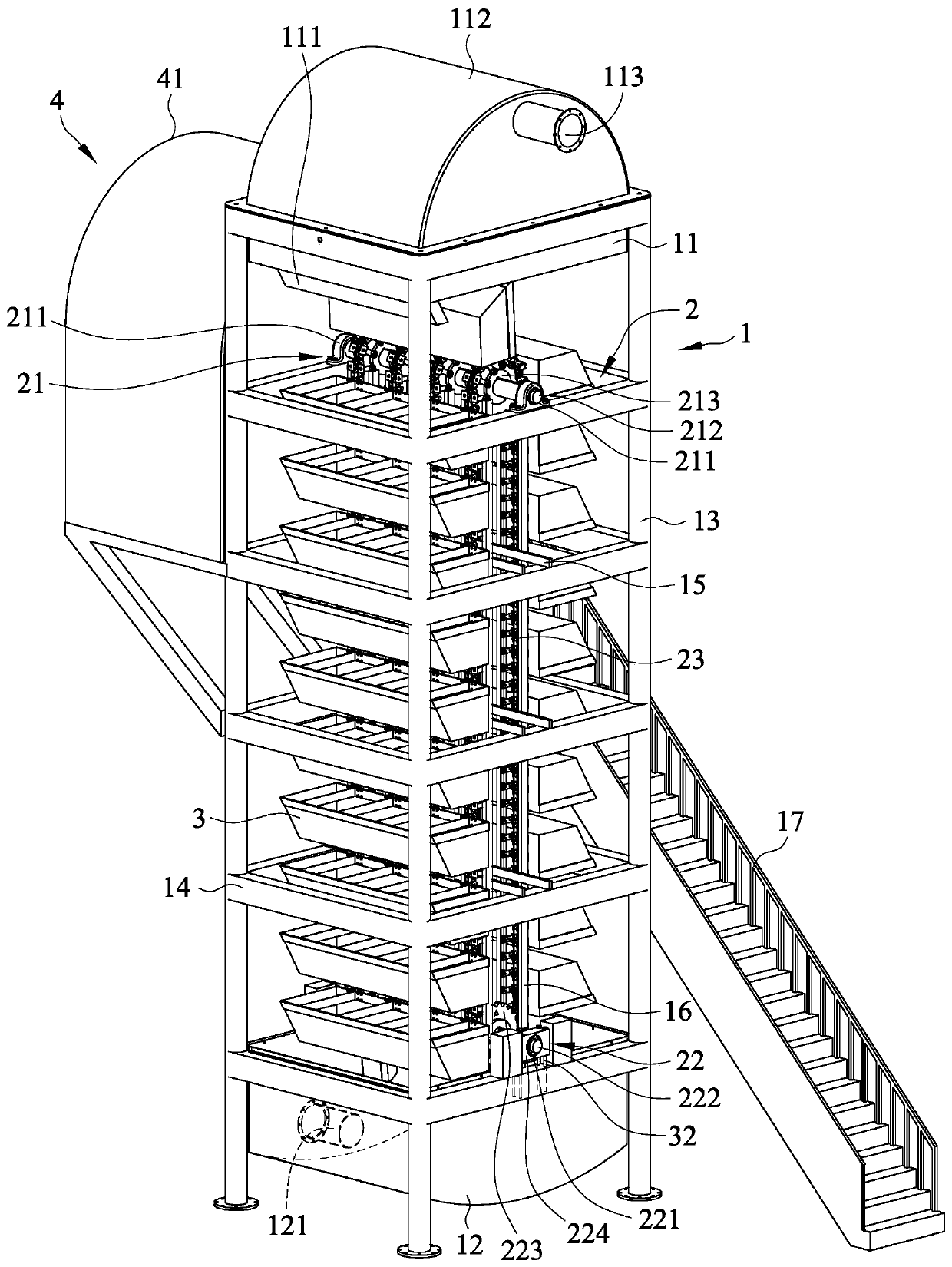
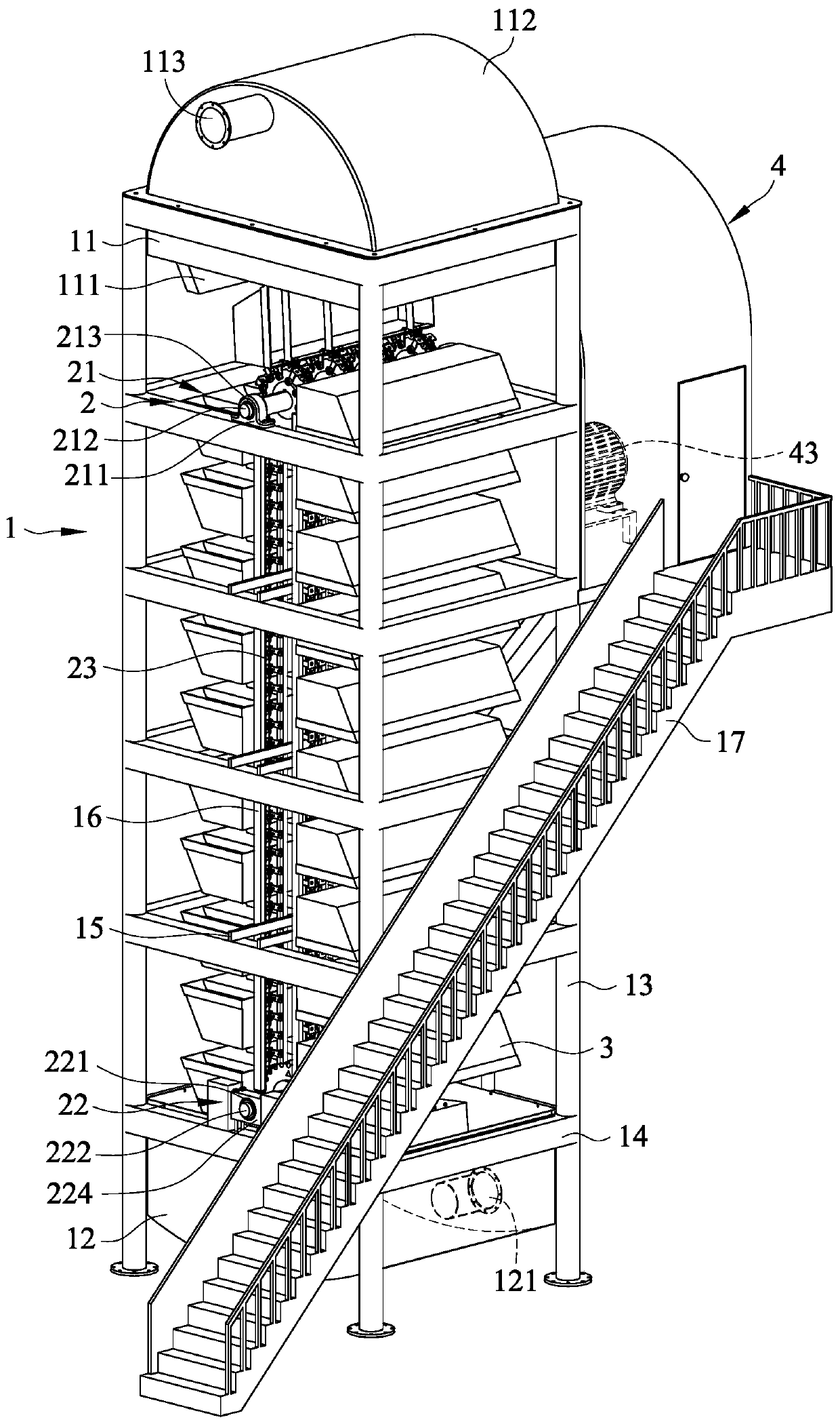
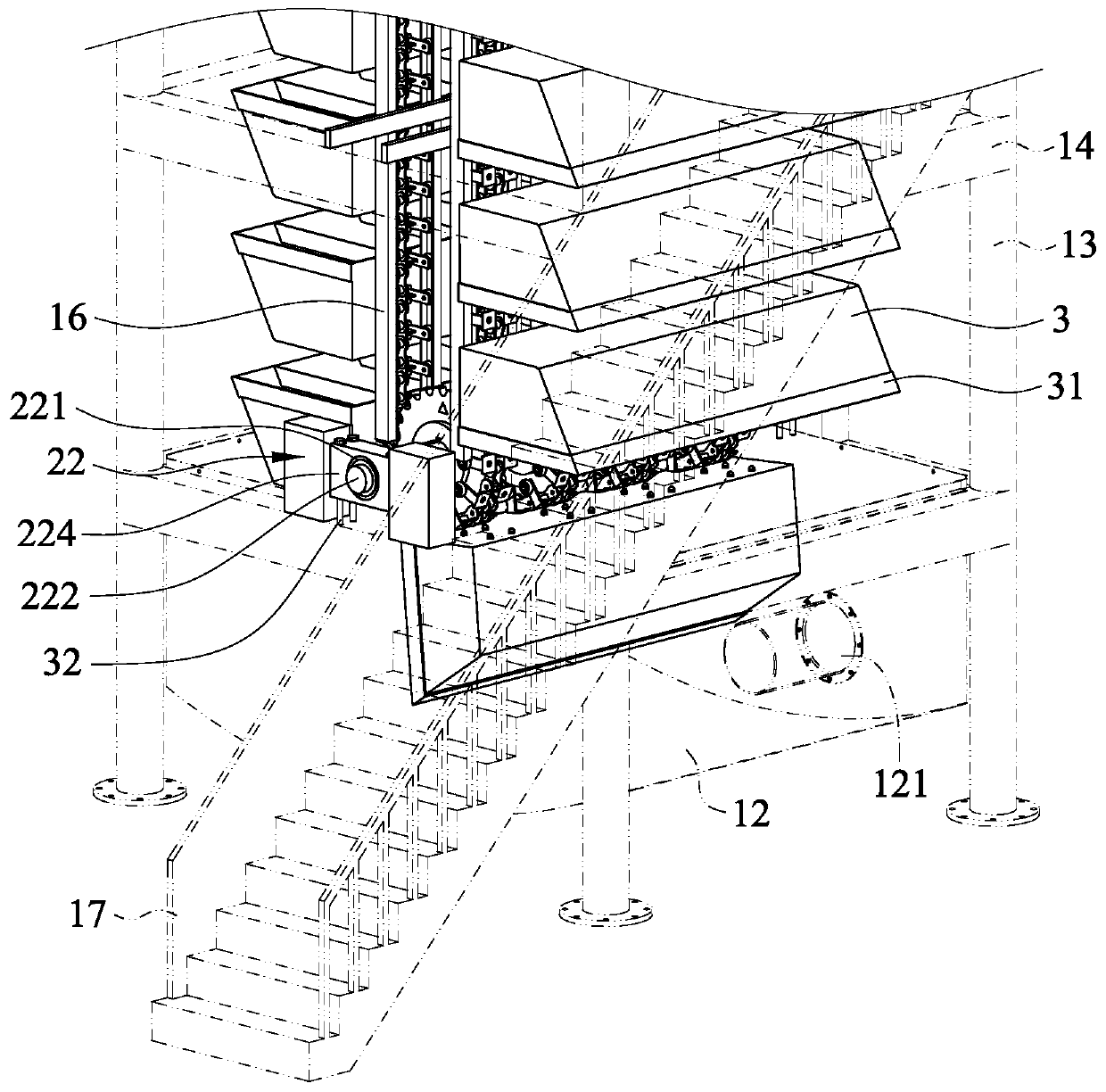
[0027] see Figure 1 to Figure 8 As shown, they are the schematic diagram of the appearance of the present invention, the schematic diagram of the appearance of another angle of the present invention, the partially enlarged schematic diagram of the top of the present invention, the partially enlarged schematic diagram of the bottom of the present invention, the schematic diagram of the first guide wheel set of the present invention, the schematic diagram of the second The schematic diagram of the guide wheel set, the schematic diagram of the combined water tank of the first guide wheel set and the second guide wheel set of the present invention, and the schematic diagram of another angle of the combined water tank of the first guide wheel set and the second guide wheel set of the present invention. As shown in the figure: a kind of vertical potential energy hydropower generation tower of the present invention, it is at least formed by a pedestal 1, a transmission mechanism 2, a...


PUM


Abstract

The invention discloses a hydroelectric power generation tower utilizing vertical potential energy. The hydroelectric power generation tower utilizing vertical potential energy comprises a seat body,a transmission mechanism, a plurality of water tanks and a power generation mechanism, wherein a water falling groove is formed in the top end of the seat body, and a water bearing groove is formed inthe bottom of the seat body; the transmission mechanism is arranged on the seat body; the water tanks are arranged on the transmission mechanism separately; and the power generation mechanism is connected with the transmission mechanism. By this, water can be injected into the water falling groove, the water falling groove is enabled to guide water into the water tank corresponding to the water falling groove, the water tanks holding water generate the potential energy of downward movement due to gravity, dynamic energy is generated by virtue of the potential energy to drive the transmissionmechanism, the transmission mechanism is enabled to generate mechanical energy due to action, and then the power generation mechanism is started to generate electric energy, so that the effects of presenting high-benefit power generation and rapid-startup power generation by virtue of a small amount of water resource, and reducing electric power for reserves through simplification for the structure of a power generation tower.

Description

technical field [0001] The invention relates to an innovation of a vertical potential energy hydroelectric power generation tower, especially through the simplification of the structure of the power generation tower, so as to achieve high-efficiency power generation with a small amount of water resources, quick start-up of power generation and reduction of standby power . Background technique [0002] The common hydroelectric power generation in public construction basically uses the way of flood discharge from reservoirs to generate power. In order to improve its power generation efficiency, it mostly relies on the impact force achieved by the water level drop (that is, the kinetic energy generated by the water level difference) to generate electricity. As energy, it drives the water flange generator to generate electricity. Therefore, this kind of hydroelectric power generation that uses reservoir flood discharge is to install the generator set at an appropriate position u...

Claims


Application Information

Patent Timeline
IPC IPC(8): F03G3/00
CPCF03G3/00
Inventor 杨健成
Owner 杨健成
Learn More