

Self-balancing type multi-loading-path one-way shearing box for pile-soil test
A self-balancing, soil test technology, applied in the direction of testing material strength by applying stable bending force, testing material strength by applying stable tension/compression, measuring devices, etc., can solve the problem of not being able to obtain experimental results, affecting stress diffusion and Attenuation and other issues, to achieve the effect of clear concept, reduced model size, and simple assembly
- Summary
- Abstract
- Description
- Claims
- Application Information
AI Technical Summary
Problems solved by technology
Method used
Image

Examples
Embodiment 1
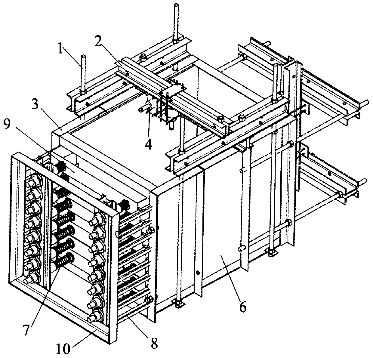
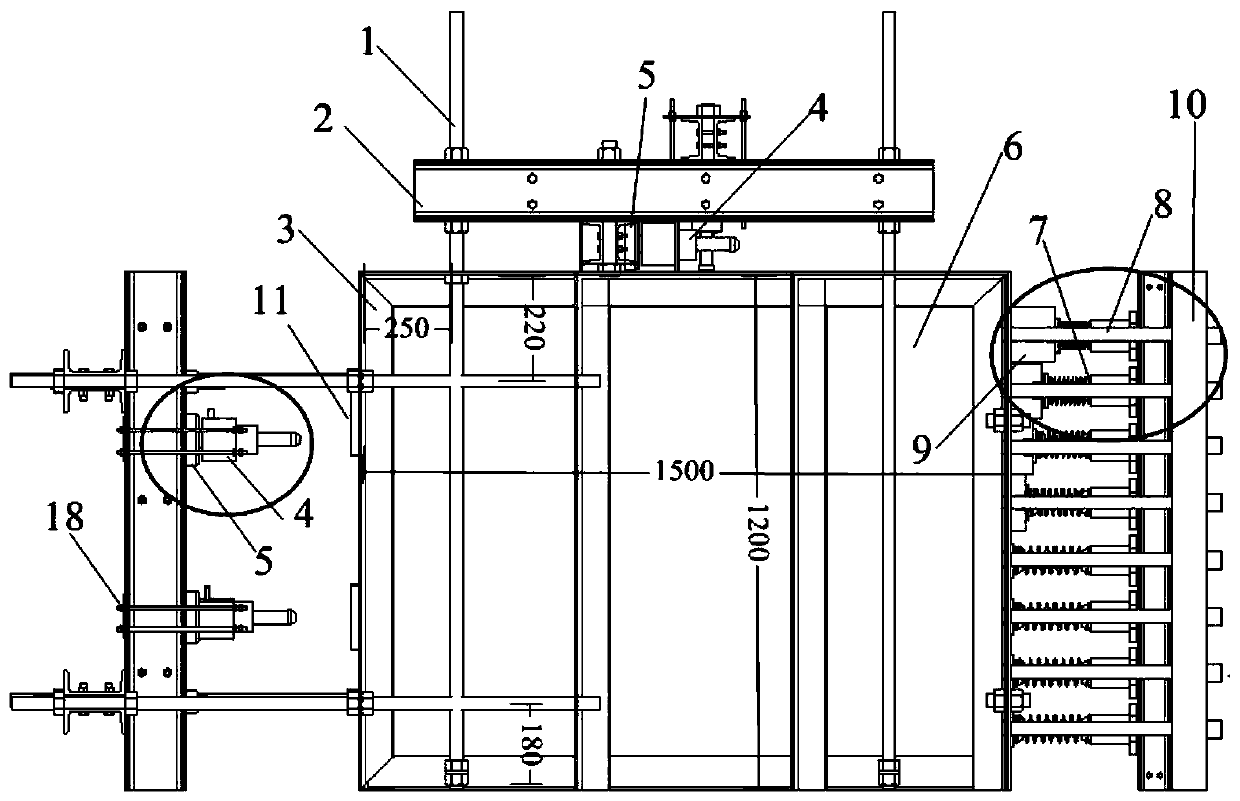
[0026] The purpose of embodiment 1 is to apply push or press down load to pile or soil body, such as Figure 1-Figure 4 shown. A self-balancing multi-loading path one-way shear box for pile-soil tests is composed of a reaction force frame, loading equipment, an angle steel box body 3 and a one-way shear device.
[0027] In this example, the reaction frame is composed of a reaction frame screw 1 and a channel steel reaction beam 2 . The counter force frame screw rod 1 passes through the hole reserved in the angle steel box body 3, and is connected with it with a nut. Two 14a-type channel steel back-to-back form the channel steel reaction beam, and bolts pass through the reserved holes to connect the two channel steels. A gap is reserved between the channel steels, the size of which is equal to the diameter of the reaction frame screw 1, and the reaction frame is formed by connecting the reaction frame screw 1 with bolts to provide reaction support for the load.
[0028] In t...
Embodiment 2
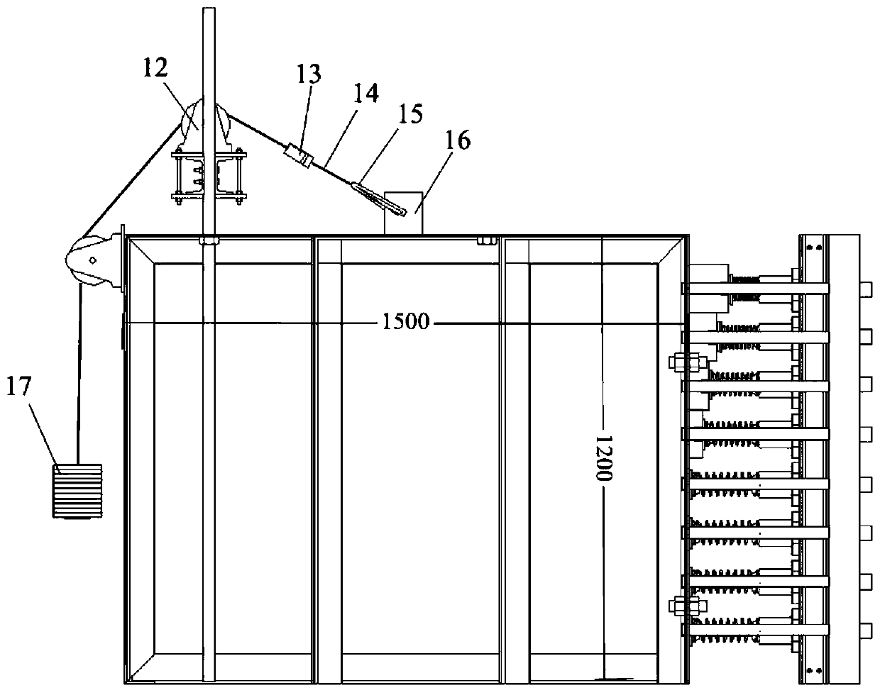
[0033] The purpose of embodiment 2 is to apply a tensile load to the pile, such as Figure 5 shown.
[0034] In this example, the angle steel box 2 and the one-way shearing device are the same as in Embodiment 1, the actuator 4 in the loading device is replaced by a pulley 12, and the connection mode with the channel steel reaction frame remains unchanged. The joint 15 passes through the pile 16 and is connected with the wire rope 14 , and the other end of the wire rope passes through the pulley 12 and is connected with the counterweight 17 , so that the pile 16 is loaded by force transmission. The tension sensor 13 is passed through the middle of the steel wire rope located at the pulley 12 and the joint 15, so that the influence of the pulley on the force transmission can be ignored, and the pulling force suffered by the stake 16 can be obtained directly. By adjusting the height of the channel steel reaction frame, the angle of the uplift load can be changed to meet differe...
PUM
 Abstract
Description
Claims
Application Information