Current transformer assembly

A technology of current transformers and components, applied in the direction of inductors, transformer/inductor shells, electrical components, etc., can solve the problems of easy failure of insulating sleeves and affect the accuracy of current transformers, and achieve the effect of avoiding the impact of accuracy

Inactive Publication Date: 2020-05-12
HENAN PINGGAO GENERAL ELECTRIC CO LTD +2
View PDF3 Cites 0 Cited by
  • Summary
  • Abstract
  • Description
  • Claims
  • Application Information

AI Technical Summary

Problems solved by technology

[0006] The purpose of the present invention is to provide a current transformer assembly to solve the technical problem in the prior art that the accuracy of the current transformer is affected due to the easy failure of the insulating sleeve

Method used


Image

  • Current transformer assembly
  • Current transformer assembly
  • Current transformer assembly

Examples


specific Embodiment 1

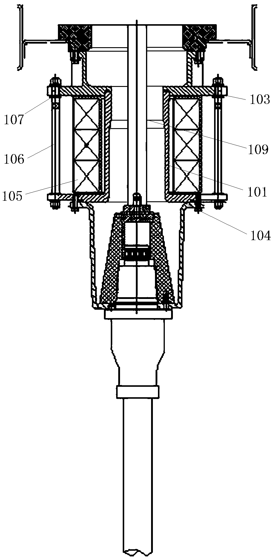
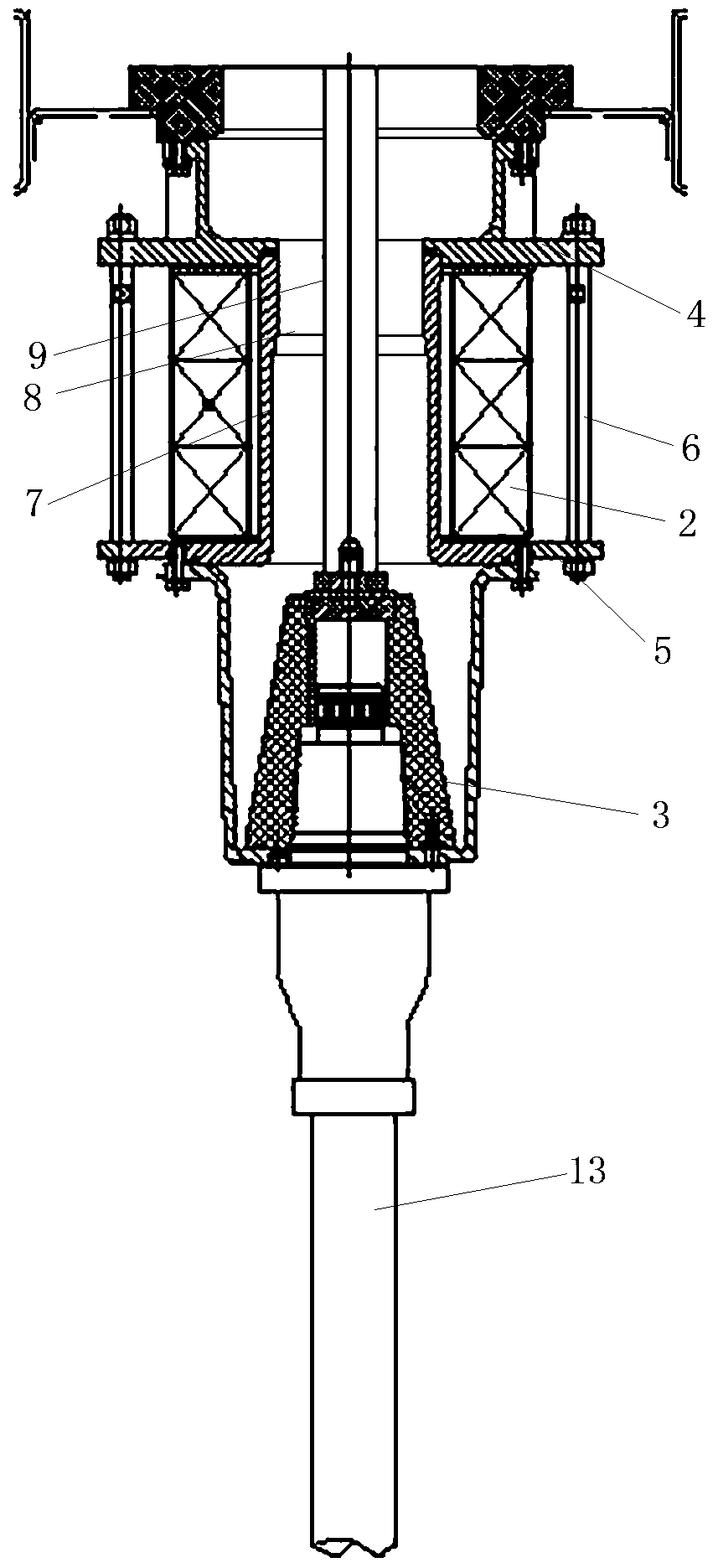
[0025] Current transformer components are used in GIS switchgear, such as figure 2 As shown, the current transformer assembly is assembled between the circuit breaker and the outlet terminal 3 of the switchgear. In other embodiments, the current transformer assembly is assembled between the circuit breaker and the inlet terminal of the switchgear.

[0026] Such as figure 2 As shown, the current transformer assembly includes a first flange 4 for fixing on the circuit breaker and a second flange 5 for fixing on the outlet terminal 3 of the switchgear, the second flange 5 and the first flange 4 Fixedly connected by threaded fasteners 6, the second flange 5 is integrally provided with a main circuit protection shell 7 near its center, and the main circuit protection shell 7 protrudes toward the first flange 4, and is connected with the first flange. 4 seal fit.

[0027] Such as figure 2 As shown, the main circuit protection shell 7 is provided with a channel 8 for the conduc...

specific Embodiment 2

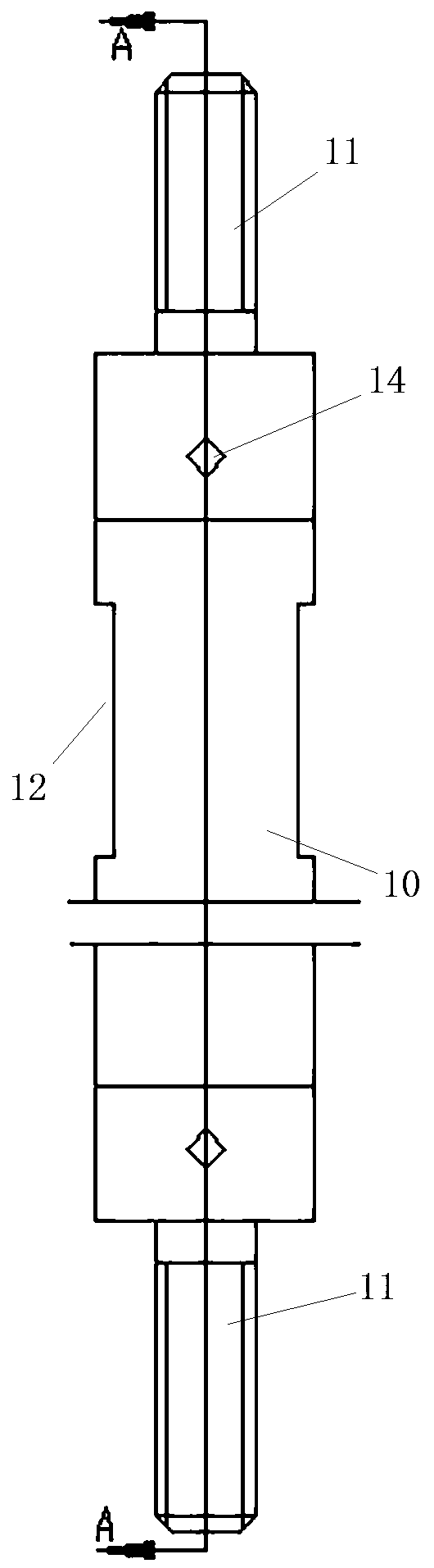
[0036] The difference from Embodiment 1 is that the metal threaded joint and the rod body are fixedly connected by bolts, so that the metal threaded joint and the rod body have better connection strength and meet the strength requirements of threaded fasteners.

specific Embodiment 3

[0038] It differs from Example 1 in that:

[0039] Before the metal threaded joint and the rod body are riveted, the metal threaded joint and the rod body may not be pre-fixed by glue. Riveted on a riveting machine.


PUM


Abstract

The invention relates to a current transformer assembly. The current transformer assembly comprises: a current transformer; a main loop protection shell which is provided with a channel for a main loop to pass through, wherein a first flange and a second flange are arranged at the two ends, in the extending direction of the channel, of the main loop protection shell respectively, and the two flanges are connected through a threaded fastener; and a current transformer which sleeves the main loop protection shell and is located between the two flanges, wherein the threaded fastener is located onthe radial outer side of the current transformer, the threaded fastener comprises a rod body and a metal threaded connector arranged at the at least one end of the rod body, and the rod body is an insulating rod body. The threaded fastener is positioned on the radial outer side of the current transformer, as the rod body of the threaded fastener is the insulating rod body, the insulating rod bodyis not easy to fail, when a current passes through a main loop, an induced current can be prevented from passing through the threaded fastener, namely, a current path is prevented from being formed on the radial outer side of the current transformer, and the influence of the induced current on the precision of the current transformer is avoided.

Description

technical field [0001] The invention relates to a current transformer assembly. Background technique [0002] GIS switchgear, that is, gas-insulated metal-enclosed switchgear, consists of circuit breakers, disconnectors, grounding switches, current transformers, voltage transformers, lightning arresters, busbars, connectors, switchgear outlets and switchgear inlets. Its compact structure, small footprint and high reliability are widely used in various fields. The current transformer is an important device in the switchgear, and its data accuracy and reliability directly affect the reliability, stability and accuracy of the switchgear. [0003] Such as figure 1 As shown, the current transformer assembly in the prior art includes a main circuit protection casing 101, and the main circuit protection casing 101 is provided with a channel for passing through the conductive rod 109, and one end of the main circuit protection casing 101 is connected with a The first flange 103 i...

Claims


Application Information

Patent Timeline
IPC IPC(8): H01F27/02H01F38/30
CPCH01F27/02H01F38/30
Inventor 高正付赵辉王焕许海超刘晓焱沈景贵张二勇
Owner HENAN PINGGAO GENERAL ELECTRIC CO LTD
Why Eureka
Try Eureka