Engineering machinery fuse burnout warning circuit
A technology of construction machinery and circuits, applied in the field of insurance burnout warning circuits, can solve problems such as warning lights not on, and achieve the effect of high reliability
- Summary
- Abstract
- Description
- Claims
- Application Information
AI Technical Summary
Problems solved by technology
Method used
Image


Examples
Embodiment Construction
[0014] The present invention will be described in further detail below in conjunction with accompanying drawing embodiment:
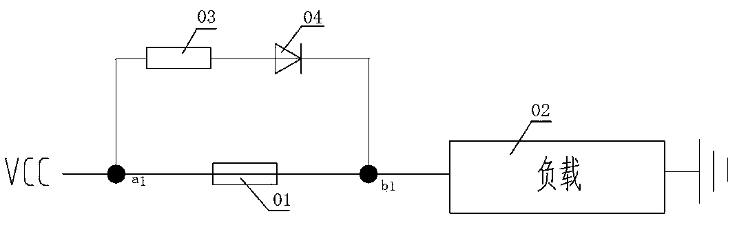
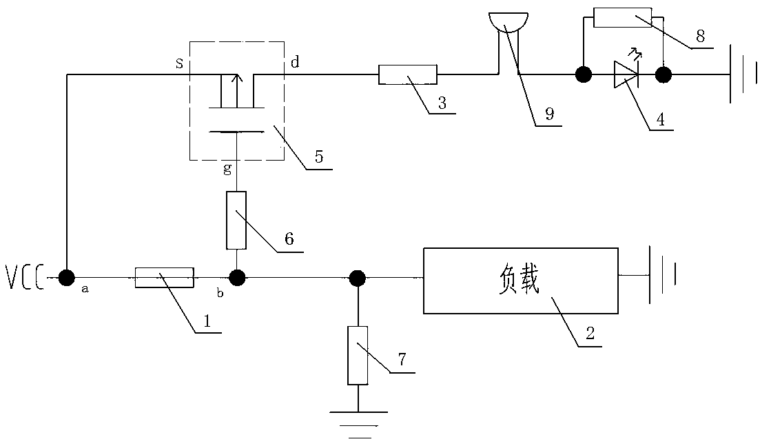
[0015] figure 2 The construction machinery fuse burning warning circuit shown includes a field effect tube 5, a current limiting resistor 3, a buzzer 9 and a warning light 4, and the current limiting resistor 3, the buzzer 9 and the warning light 4 are sequentially connected to the field effect tube 5 Between the drain D and the ground wire, a shunt resistor 8 is connected in parallel at both ends of the warning light 4; the field effect tube 5 is a PMOS field effect tube; the warning light 4 is an LED light-emitting diode; the source S of the field effect tube 5 It is connected to the power supply and the power terminal a of the fuse 1, the load terminal b of the fuse 1 is connected to the gate g of the field effect transistor 5 through the input resistor 6, and the load terminal b of the fuse 1 is connected to the ground wire through the pull-down re...
PUM
 Abstract
Description
Claims
Application Information
PatSnap Eureka turns technology decisions into work you can execute. Powered by our Innovation Knowledge Graph, it runs expert workflows across engineering, life sciences, materials and intellectual property. Get your review-ready output in minutes.


