
Novel chuck

A chuck, a new type of technology, applied in the direction of the chuck, can solve the problems of increasing the burden on the spindle and bearing of the machine tool, affecting the processing accuracy of the product, affecting the stability of the machine tool, etc., and achieving convenient and clear adjustment, reduced overall weight, and simple structure. Effect

Active Publication Date: 2020-05-15
上饶广信区高灵机械科技有限公司
View PDF7 Cites 7 Cited by
  • Summary
  • Abstract
  • Description
  • Claims
  • Application Information

AI Technical Summary

Problems solved by technology

[0004] After the research and development is completed, it is put into the market. When it is used, it is reported that the weight is heavy, which increases the burden on the machine tool spindle and bearings, affects the stability of the machine tool and thus affects the processing accuracy of the product, and there are also shortcomings such as high precision and difficult processing of the main internal parts. It has made further optimization improvements

Method used


Image

  • Novel chuck
  • Novel chuck
  • Novel chuck

Examples


Embodiment Construction

[0053] The specific implementation manners of the present invention will be further described in detail below in conjunction with the accompanying drawings and embodiments. The following examples are used to illustrate the present invention, but are not intended to limit the scope of the present invention.

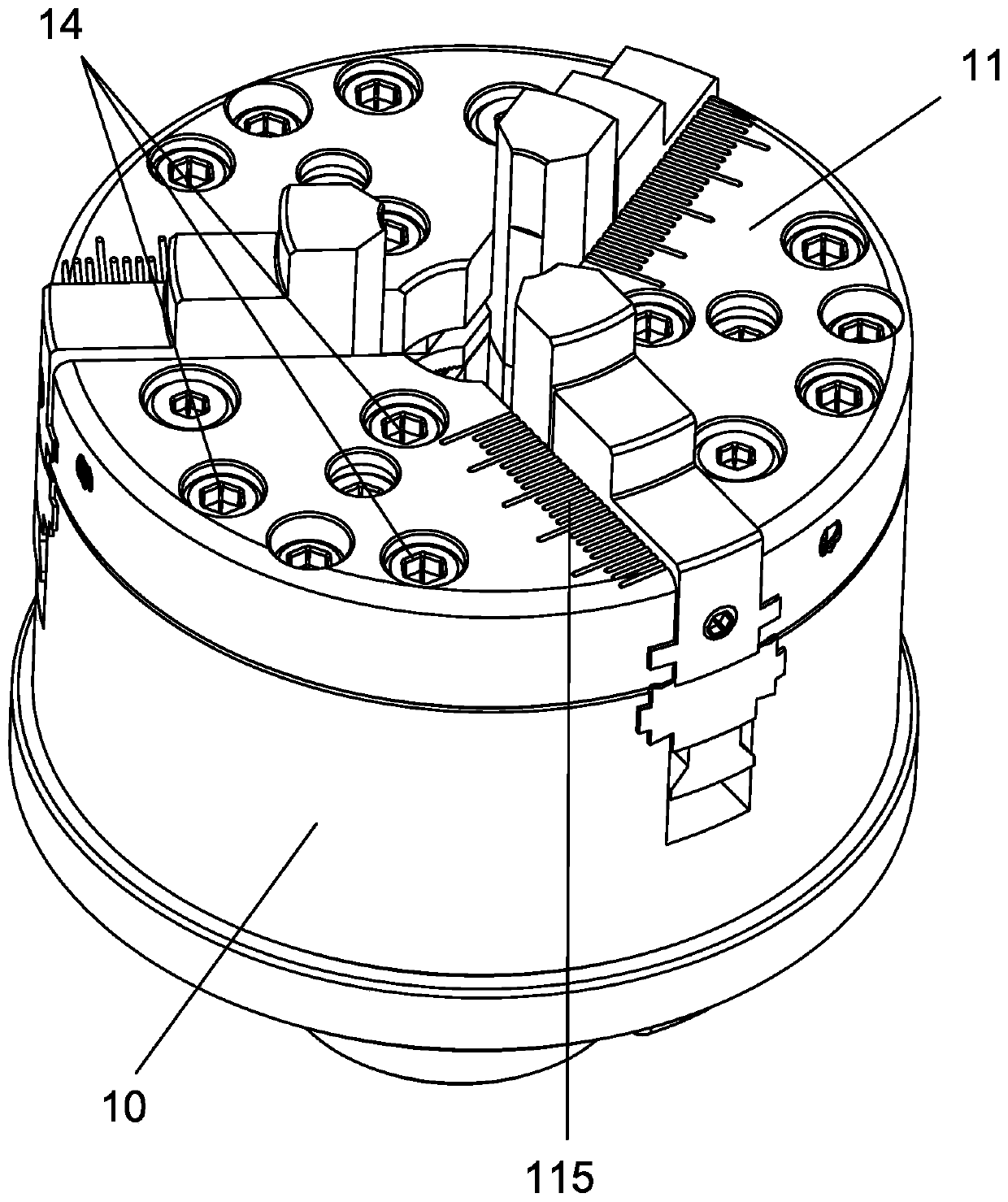
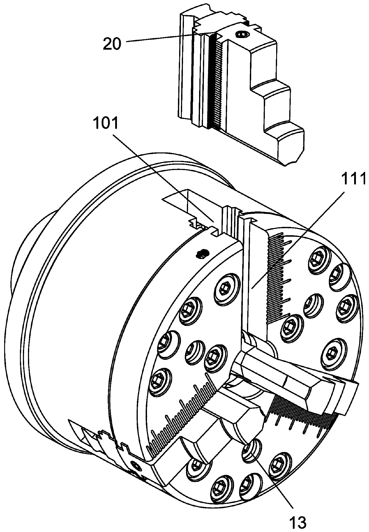
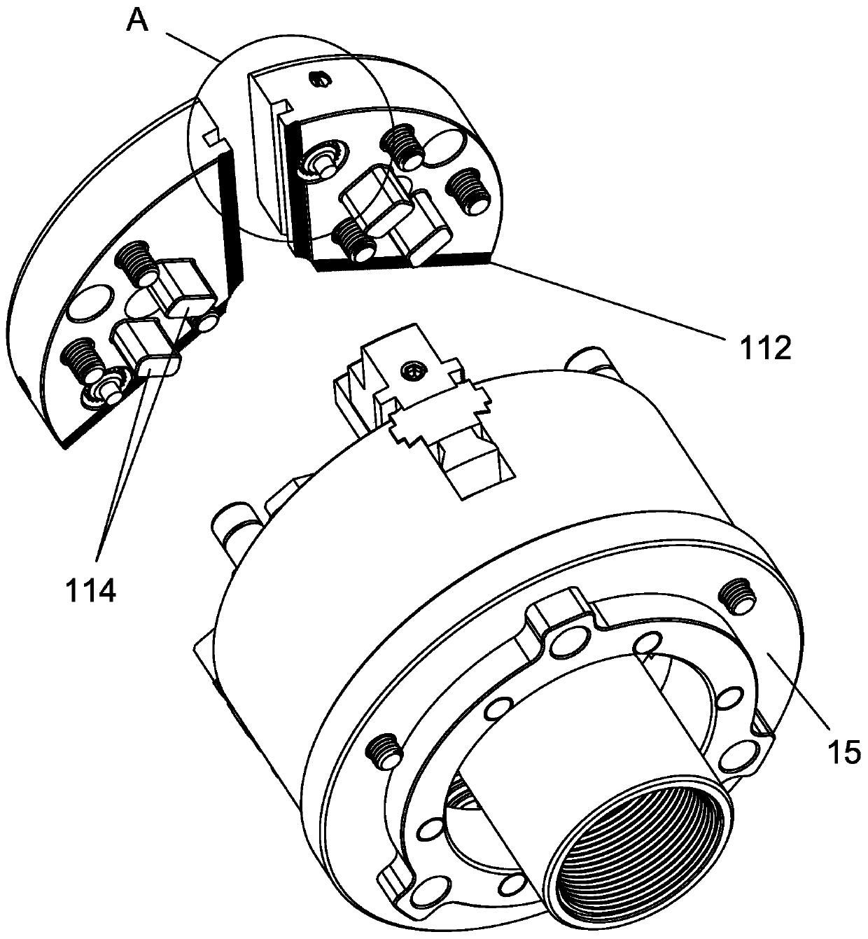
[0054] refer to Figure 1 to Figure 13 ,Such as Figure 1 to Figure 13 A new type of chuck shown includes a housing 10, jaw assemblies 20 uniformly distributed along the circumferential direction of the housing 10, the end surface of the housing 10 is provided with a jaw locking cover 11, and the jaw assembly 20 slides in the radial direction relative to the housing 10 to adjust to the required clamping size and is fixed by the claw locking cover 11; the housing 10 is equipped with a clamping drive device (not shown) The control panel 12, the jaw assembly 20 is controlled by the control panel 12, so that it can be clamped or loosened on the above-mentioned clamping size;...


PUM


Abstract

The invention provides a novel chuck. The novel chuck comprises a shell and clamping jaw assemblies which are arranged in the circumferential direction of the shell in an evenly-distributed mode. Thenovel chuck is characterized in that a clamping jaw locking cover is arranged on the end face of the shell, the clamping jaw assemblies slide relative to the radial direction of the shell so as to beadjusted to the required clamping size and fixed through the clamping jaw locking cover; and a control disc connected with a clamping driving device is arranged in the shell, and the clamping jaw assemblies are controlled through the control disc to realize clamping or loosening within the clamping size. According to the novel chuck, the overall weight is greatly reduced, meanwhile the structure is simpler, assembly and machining are convenient, the production cost is greatly lowered, compared with an existing oil pressure chuck, higher strength and clamping intensity are achieved, self-centering clamping and eccentric clamping can be achieved, the application range is wide, and compared with an existing instrument lathe clamp, the advantages that the adjusting range of the clamping size is large, and a clamping head does not need to be replaced are achieved.

Description

technical field [0001] The invention relates to the field of clamping of machines such as numerical control machine tools, bench drills, vertical drills, milling machines, numerical control engraving and milling, and in particular to a novel chuck. Background technique [0002] Fixtures are used in mechanical lathes to clamp workpieces and then process them. The structure of the existing lathe clamps generally includes a jaw movable cover and a spiral disk. A through hole is arranged in the center of the jaw movable cover, and a walking rail connected with the through hole is arranged on the cover surface of the jaw movable cover. Claws are provided for sliding on the walking rail, and the back of the claws is provided with a helical tooth groove that cooperates with the helical disc. Through the rotation of the helical disc, the claws slide toward each other or relative to each other in the traveling rail to realize the clamping and uninstall. [0003] The applicant appli...

Claims


Application Information

Patent Timeline
Patent Type & Authority Applications(China)
IPC IPC(8): B23B31/16B23B31/103
CPCB23B31/103B23B31/16087
Inventor 曹宇曹正虎
Owner 上饶广信区高灵机械科技有限公司
Learn More