Manipulator guide method and device based on 3D machine vision

A technology of machine vision and manipulator, which is applied in the field of manipulator guidance of 3D machine vision, can solve problems such as low engineering efficiency, high technical difficulty of feature points, and difficulty in quickly obtaining attitudes, etc.

Active Publication Date: 2020-05-15
群滨智造科技(苏州)有限公司
View PDF10 Cites 11 Cited by
  • Summary
  • Abstract
  • Description
  • Claims
  • Application Information

AI Technical Summary

Problems solved by technology

[0007] However, the problem with the above scheme is that the template method is often used to calculate the offset between the relevant position and the standard template in the visual deviation correction part and output it to the manipulator. In this process, the existing manual teaching or offline programming is not fully utilized. The manipulator trajectory needs to manually number the trajectory points and make them correspond to the offset provided by the vision, so the engineering efficiency is low and the degree of intelligence is not high
[0008] When it comes to the required processing trajectory is extremely complex, especially when the posture requirements are relatively high, it is difficult to quickly obtain the required posture and relevant feature points in general offline trajectory programming software and trajectory editing software using machine vision systems. technically difficult issues

Method used


Image

  • Manipulator guide method and device based on 3D machine vision
  • Manipulator guide method and device based on 3D machine vision
  • Manipulator guide method and device based on 3D machine vision

Examples


Embodiment Construction

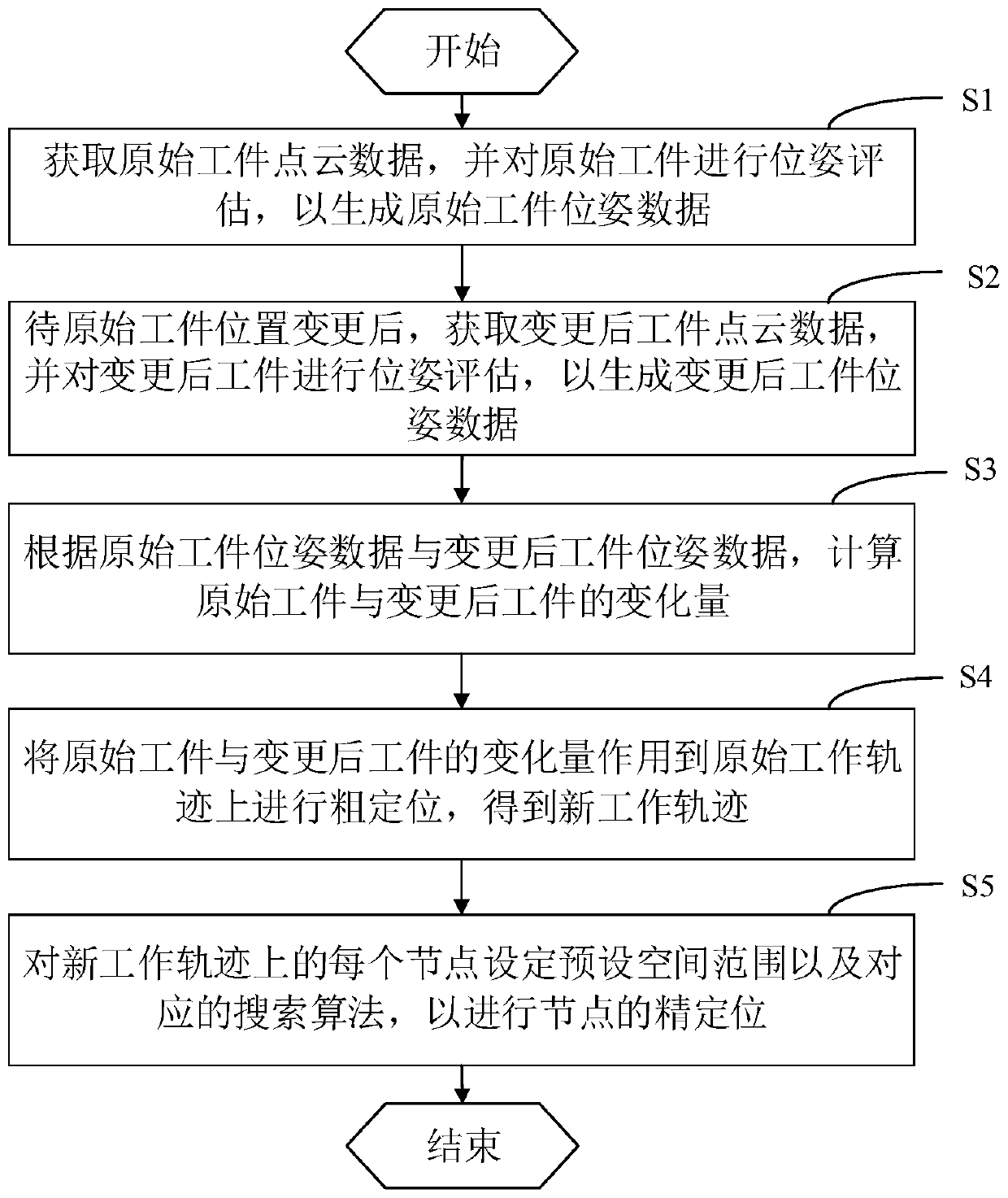
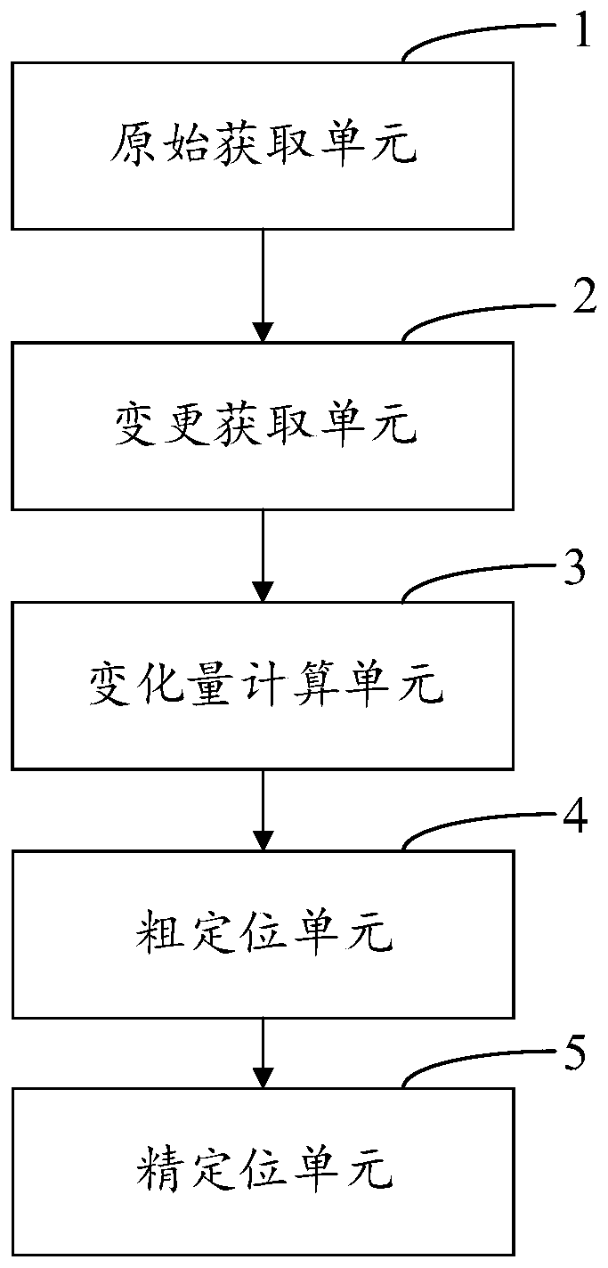
[0041] It should be understood that the specific embodiments described here are only used to explain the present application, and are not intended to limit the present application.

[0042] The technical solutions in the embodiments of the application will be clearly and completely described below in conjunction with the accompanying drawings in the embodiments of the application. Obviously, the described embodiments are only part of the embodiments of the application, not all implementations example. Based on the embodiments in this application, all other embodiments obtained by persons of ordinary skill in the art without creative efforts fall within the protection scope of this application.

[0043] It should be noted that the terms "comprising", "comprising" and "having" in the specification and claims of the present application and the above drawings and any variations thereof are intended to cover non-exclusive inclusion. For example, a process, method, system, product ...


PUM


Abstract

The invention provides a manipulator guide method and device based on 3D machine vision, and is applied to the technical field of manipulator control. The method comprises the steps that point cloud data of an original workpiece are obtained, and the original workpiece is subjected to pose evaluation so that pose data of the original workpiece can be generated; after the position of the original workpiece is changed, point cloud data of the workpiece after change are obtained, and the changed workpiece is subjected to pose evaluation so that pose data of the workpiece after change can be obtained; and the pose variable quantity before and after change is calculated and acts on an original working track planned on the original workpiece to obtain a coarse positioning track, and then, a track after precise positioning is obtained through a preset spatial range and a point position search algorithm for each track point of the coarse positioning track. Thus, the working track of a manipulator can be quickly guided into a system, a quick track switching working mode is included, the process of conducting track guide on the manipulator through machine vision is simplified, and the work amount for switching different operation tracks is decreased.

Description

technical field [0001] The present application relates to the technical field of manipulator control, in particular to a 3D machine vision manipulator guidance method and device. Background technique [0002] In the manufacturing industry, manipulators are commonly used in two scenarios, one for point-to-point operations and the other for continuous trajectory operations; in these two scenarios: [0003] When it comes to the non-negligible contour difference of the processed object itself, machine vision technology is usually used to correct it. In most cases, due to problems such as production capacity, space interference, and equipment budget, it is impossible to pass multiple The contour information of all angles can be obtained by using a single camera or multiple cameras at a time to collect multiple angles of the workpiece, which makes pure visual trajectory planning impossible, and must be obtained by manual teaching or offline programming. job track. [0004] There...

Claims


Application Information

Patent Timeline
Patent Type & Authority Applications(China)
IPC IPC(8): B25J9/16
CPCB25J9/1664B25J9/1697B25J9/1602Y02P90/30
Inventor 席豪圣陈方
Owner 群滨智造科技(苏州)有限公司
Why Eureka
Try Eureka