
Internal edge sealing device

A technology of edge banding equipment and edge banding machine, which is applied to wood processing appliances, household components, etc., can solve the problems of large size, skew, time-consuming and labor-intensive edge banding equipment, and achieves improved edge banding efficiency, reduced equipment costs, The effect of simplifying the size and structure of the equipment

Pending Publication Date: 2020-05-15
NOVAH SHANGHAI OFFICE SYST
View PDF0 Cites 2 Cited by
  • Summary
  • Abstract
  • Description
  • Claims
  • Application Information

AI Technical Summary

Problems solved by technology

[0002] After some products are cut, it is necessary to seal the cutting surface to prevent wood thorns from being scratched and improve the appearance of the product. It is very simple to perform edge sealing on the outer cutting surface of some products, but some products are on the other side. There is a through hole in the center or other positions. When the through hole is sealed inside, there will be problems, because the existing edge banding machines are equipped with glue coating devices, which use glue to stick the edge on the product. As a result, the volume of the edge banding equipment is large, so if the through hole is large, you can try to use an external edge banding device for edge banding, but if you encounter a small through hole, you can only perform manual edge banding, and manual edge banding not only consumes It is time-consuming and labor-intensive, and it is also prone to unqualified situations such as skewing

Method used


Image

  • Internal edge sealing device
  • Internal edge sealing device
  • Internal edge sealing device

Examples


Embodiment Construction

[0014] The present invention will be further described in conjunction with the accompanying drawings.

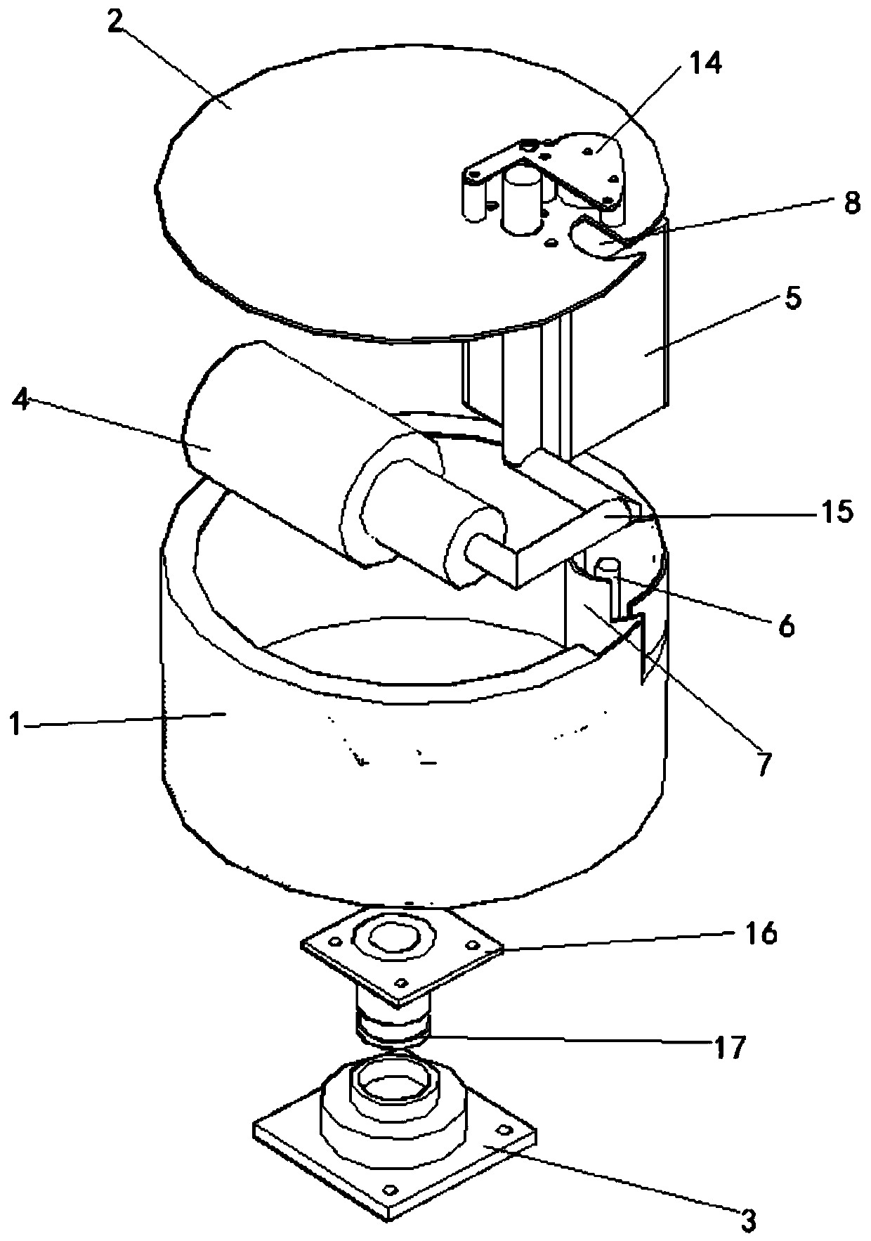
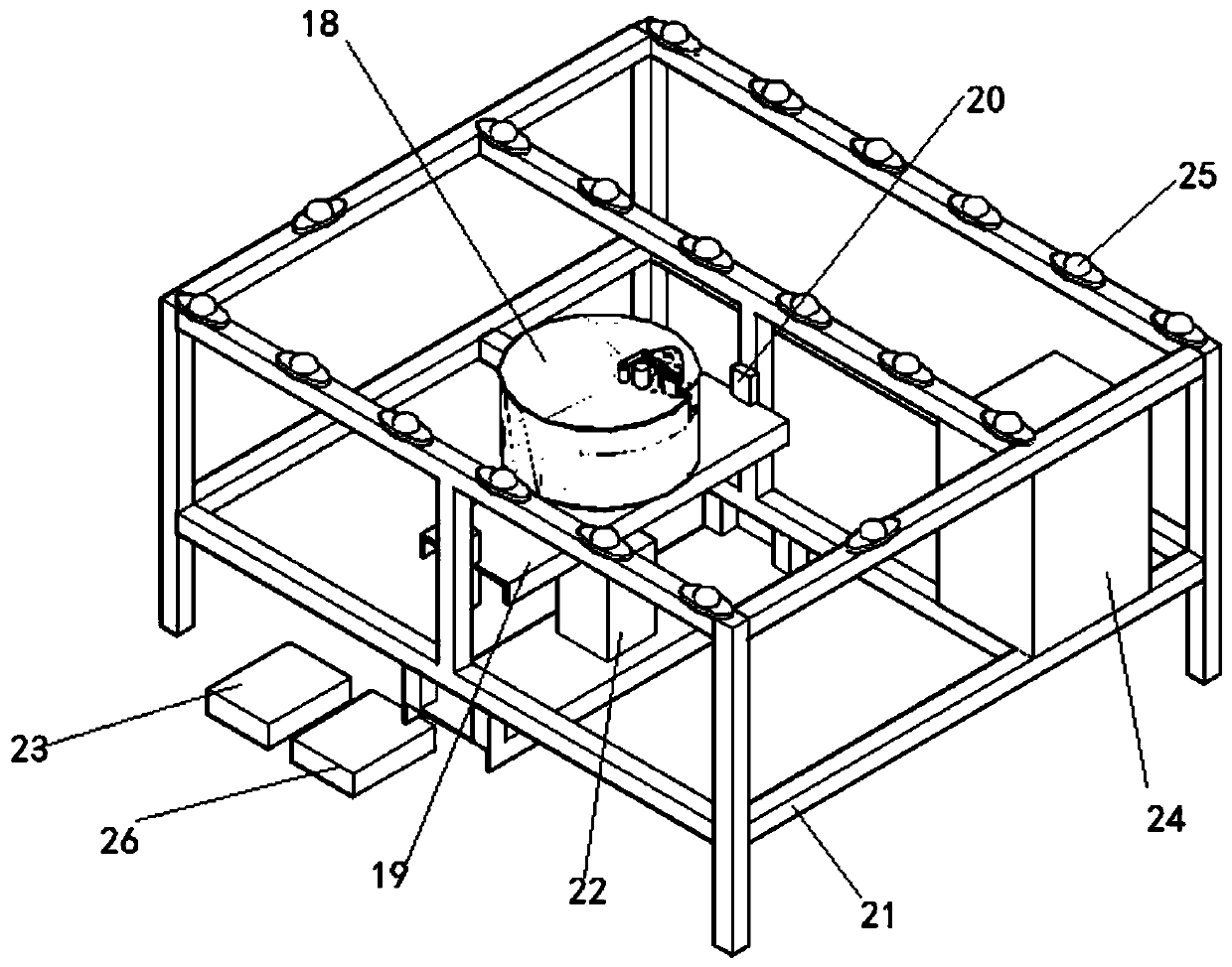
[0015] see Figure 1~4 , the present invention designs an inner edge banding device, including: an edge banding machine, characterized in that: the edge banding machine 18 includes an outer shell 1, an upper cover 2, and a bearing seat 3, and the outer shell 1 is installed with Adjustable blower 4, motor 5 and roller 3 6, the position of roller 3 6 is close to the inner wall of the outer casing 1, and a semi-arc guide plate 7 is provided beside the roller 3 6, and the edge of the upper cover 2 is provided with a semicircular Recessed groove 8, one side of semicircular recessed groove 8 is fixed with roller one 9, one side of roller one 9 close to the center of the upper cover 2 is fixed with roller two 10, next to roller two 10 is fixed with transmission shaft 11, The power shaft 12 is fixed beside the transmission shaft 11, and the side position of the power shaft 12 is fi...


PUM


Abstract

The invention relates to the technical field of mechanical equipment, in particular to an internal edge sealing device. The internal edge sealing device comprises an edge sealing machine. An adjustable air blower, a motor and a roller III are arranged in an outer shell, and a half-arc-shaped guide plate is arranged near the roller III. A semicircular groove is formed in the edge of an upper cover,and a roller I is fixedly arranged on one side of the semicircular groove. A roller II is fixedly arranged on one side of the roller I, and a transmission shaft is fixedly arranged near the roller II. A power shaft is fixedly arranged near the transmission shaft, and a glue pressing roller is fixedly arranged near the power shaft. An air pipe is arranged between the glue pressing roller and the semicircular groove, and the lower part of the air pipe is connected with the adjustable air blower. The lower part of the power shaft is connected with the motor. A rotation shaft is fixedly arrangedon the outer side face of the bottom surface in the outer shell, and the other end of the rotation shaft is fixed on a bearing seat. The internal edge sealing device uses mechanical edge sealing instead of manual edge sealing, cancels gluing equipment, simplifies the volume and structure of the equipment, reduces the equipment cost, and improves the edge sealing efficiency.

Description

technical field [0001] The invention relates to the technical field of mechanical equipment, in particular to an inner edge banding equipment. Background technique [0002] After some products are cut, it is necessary to seal the cutting surface to prevent wood thorns from being scratched and improve the appearance of the product. It is very simple to perform edge sealing on the outer cutting surface of some products, but some products are on the other side. There is a through hole in the center or other positions. When the through hole is sealed inside, there will be problems, because the existing edge banding machines are equipped with glue coating devices, which use glue to stick the edge on the product. As a result, the volume of the edge banding equipment is large, so if the through hole is large, you can try to use an external edge banding device for edge banding, but if you encounter a small through hole, you can only perform manual edge banding, and manual edge bandi...

Claims


Application Information

Patent Timeline
Patent Type & Authority Applications(China)
IPC IPC(8): B27N7/00
CPCB27N7/00
Inventor 姚国林
Owner NOVAH SHANGHAI OFFICE SYST
Learn More