Ceramic mold uniform grouting frame

A ceramic mold, uniform technology, applied in the field of grouting racks, can solve the problems of troublesome operation and low work efficiency, and achieve the effect of convenient operation and high work efficiency

Inactive Publication Date: 2020-05-15
DEHUA COUNTY LIDE HOUSEHOLD ARTICLE CO LTD
View PDF1 Cites 1 Cited by
  • Summary
  • Abstract
  • Description
  • Claims
  • Application Information

AI Technical Summary

Problems solved by technology

[0005] The purpose of the present invention is: to overcome the need for people to pour the slurry into the mold, which is troublesome to operate and lead to low work efficiency, and to provide a machine that can replace manual slurry into the mold, which is easy to operate and high in work efficiency. Ceramic mold uniform grouting frame

Method used


Image

  • Ceramic mold uniform grouting frame
  • Ceramic mold uniform grouting frame
  • Ceramic mold uniform grouting frame

Examples


Embodiment 1

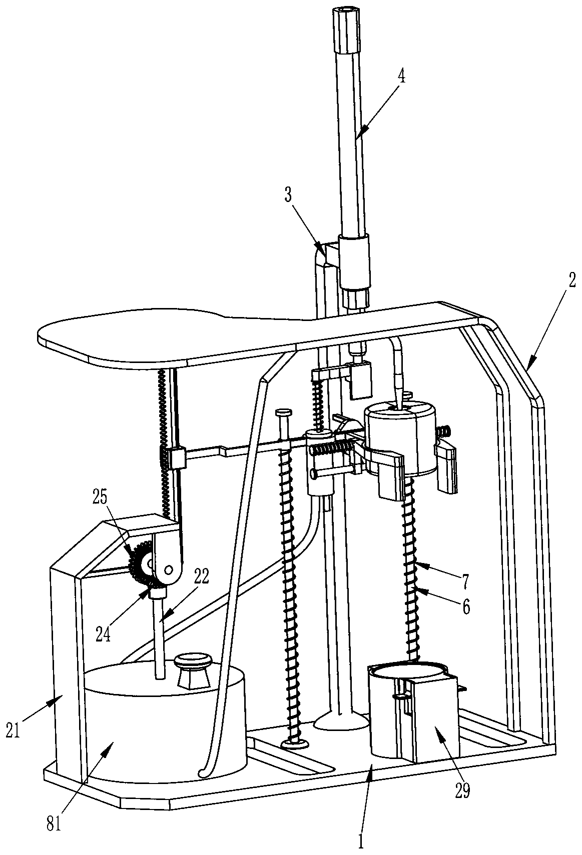
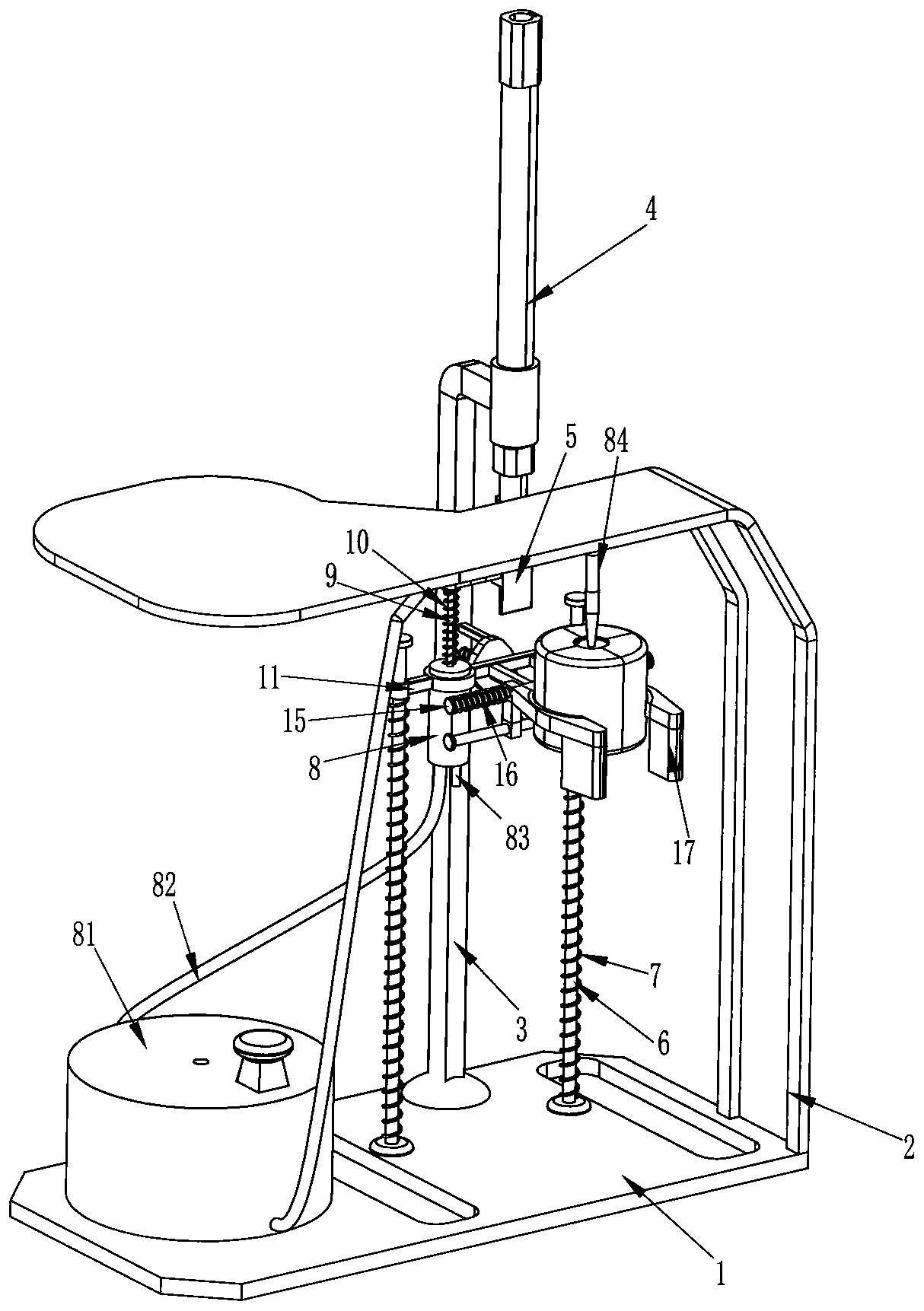
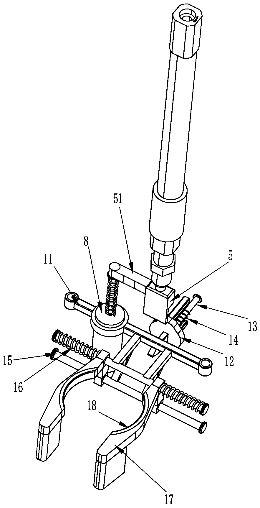
[0024] see Figure 1-Figure 3 , a uniform grouting frame for ceramic molds, including a base 1, a frame 2, a support rod 3, a cylinder 4, a driving mechanism, a charging box 81, a grouting pipe 84 and a clamping mechanism, and the front part on the right side of the top of the base 1 is fixed Connected to the frame 2, the top right side of the frame 2 is fixedly connected with a spray pipe 84, the top left side of the base 1 is installed with a charging box 81, and the lower part of the front side of the charging box 81 is connected and communicated with one end of the spray pipe 84 , the rear part of the right side of the top of the base 1 is fixedly connected with a support rod 3, and the rear end of the support rod 3 is fixedly connected with a cylinder 4, and the right side of the top of the base 1 is provided with a drive mechanism, which is connected with the telescopic rod of the cylinder 4, and the drive mechanism is also connected with the telescopic rod of the cylinde...

Embodiment 2

[0031] see figure 1 , Figure 4 and Figure 5 Compared with Embodiment 1, the main difference of this embodiment is that in this embodiment, it also includes a guide sleeve 19, a rack 20, a fixed frame 21, a connecting plate 211, a rotating shaft 22, a stirring plate 23, a straight bevel gear 24, Two-way special-shaped gear 25, folding lever 26, wedge-shaped block 27 and the fifth spring 28, base 1 top left rear part is fixedly connected with fixed frame 21, and fixed frame 21 inner top right front part is fixedly connected with connecting plate 211, connecting plate 211 bottoms are rotatably connected with bidirectional special-shaped gear 25, and the middle rotatable of charging box 81 top is connected with rotating shaft 22, and the bottom end of rotating shaft 22 is affixed with agitating plate 23, and the top of revolving shaft 22 is affixed with straight-toothed bevel gear 24. The bevel gear 24 is located at the front side of the two-way special-shaped gear 25 and mesh...

Embodiment 3

[0034] see figure 1 and Figure 6 , compared with embodiment 1 and embodiment 2, the main difference of this embodiment is that in this embodiment, it also includes a placement block 29, a support plate 30, a sixth spring 31, an L-shaped rotating block 32 and a torsion spring 33, and the base 1 The front part on the right side of the top is fixedly connected with a placement block 29, and a sliding support plate 30 is provided in the placement block 29. A sixth spring 31 is connected between the bottom of the support plate 30 and the inner bottom of the placement block 29, and the left and right sides of the placement block 29 Both sides tops are all hinged with L-shaped rotating block 32, and the hinge of L-shaped rotating block 32 and placement block 29 is provided with torsion spring 33.

[0035] When the clamp block 17 drives the mold to move downward, the mold moves downward to contact the support plate 30. Due to the action of the sixth spring 31, the support plate 30 b...


PUM


Abstract

The invention relates to a grouting frame, in particular to a ceramic mold uniform grouting frame. The technical problem is how to design the ceramic mold uniform grouting frame which can replace manpower to fill a mold with slurry and is convenient to operate and high in working efficiency. The ceramic mold uniform grouting frame comprises a base, wherein a rack is fixedly connected to the edge of one side of the base, the rack is in an L shape, a supporting rod is mounted on one side of the base and is close to the rack, and an air cylinder is vertically mounted at the tail end of the supporting rod. According to the grouting frame, the slurry is poured into a charging box, then the mold is moved to the potion between clamping blocks on two sides to be clamped and fixed, a telescopic rodof the starting air cylinder is stretched, and a proper amount of slurry is sprayed into the mold through a slurry spraying pipe. Meanwhile, the clamping blocks drive the mold loaded with the slurryto move downwards, and the slurry does not need to be poured into the mold manually, so that operation is convenient, and the working efficiency is high.

Description

technical field [0001] The invention relates to a grouting frame, in particular to a ceramic mold uniform grouting frame. Background technique [0002] Ceramics, the Chinese invented pottery as early as about 8000-2000 BC (Neolithic Age). The utensils fired with clay are called pottery, and the utensils fired with china clay are called porcelain. Ceramics is the general term for pottery, stoneware and porcelain. The ancients called ceramics Ou. Any utensils made of two different types of clay, pottery clay and porcelain clay, after batching, molding, drying, roasting and other processes can be called ceramics. In the production of ceramics, they all need to be shaped, so they need to be An appropriate amount of slurry is poured into the corresponding mold and left for a period of time, and the slurry hardens to form ceramics. [0003] Existing grouting racks, such as the Chinese patent whose patent notification number is CN206201171U discloses a conveniently foldable cer...

Claims


Application Information

Patent Timeline
Patent Type & Authority Applications(China)
IPC IPC(8): B28B1/24B28B13/02
CPCB28B1/24B28B13/0235
Inventor 刘美苹
Owner DEHUA COUNTY LIDE HOUSEHOLD ARTICLE CO LTD
Why Eureka
Try Eureka