Pressure relief device and elevator

A pressure relief device and pressure relief technology, applied in elevators, transportation and packaging in buildings, etc., can solve the problems of difficulty in opening elevator landing doors, poor passenger waiting experience and high cost

Active Publication Date: 2020-05-15
HITACHI ELEVATOR CHINA
View PDF8 Cites 2 Cited by
  • Summary
  • Abstract
  • Description
  • Claims
  • Application Information

AI Technical Summary

Problems solved by technology

[0003] Based on this, it is necessary to provide a pressure relief device and an elevator, aiming to solve the problems of difficulty in opening elevator landing doors caused by the chimney effect in the prior art, poor passenger waiting experience, and high cost

Method used


Image

  • Pressure relief device and elevator
  • Pressure relief device and elevator
  • Pressure relief device and elevator

Examples


Embodiment Construction

[0032] In order to make the object, technical solution and advantages of the present invention clearer, the present invention will be further described in detail below in conjunction with the accompanying drawings and specific implementation methods. It should be understood that the specific embodiments described here are only used to explain the present invention, and do not limit the protection scope of the present invention.

[0033] It should be noted that when an element is referred to as being “fixed on”, “disposed on” or “installed on” another element, it may be directly on the other element or there may be an intervening element. When an element is considered to be "connected" to another element, it may be directly connected to the other element or there may be an intervening element at the same time; the specific way that one element is fixedly connected to another element can be realized through existing technologies, and will not be discussed here. To repeat it agai...


PUM


Abstract

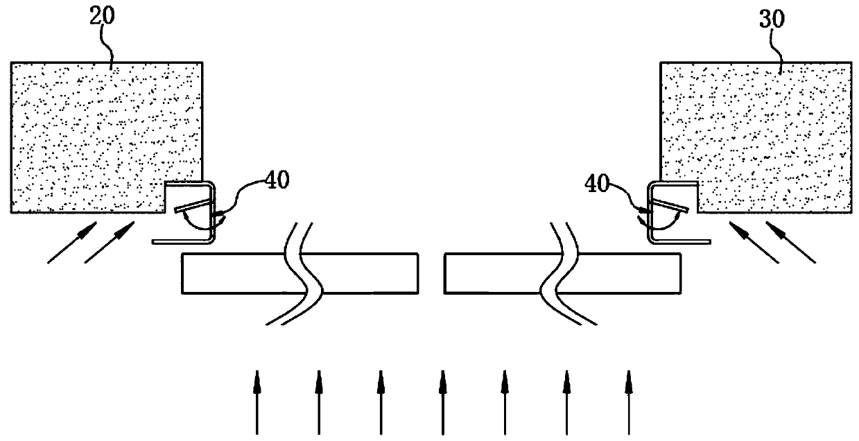
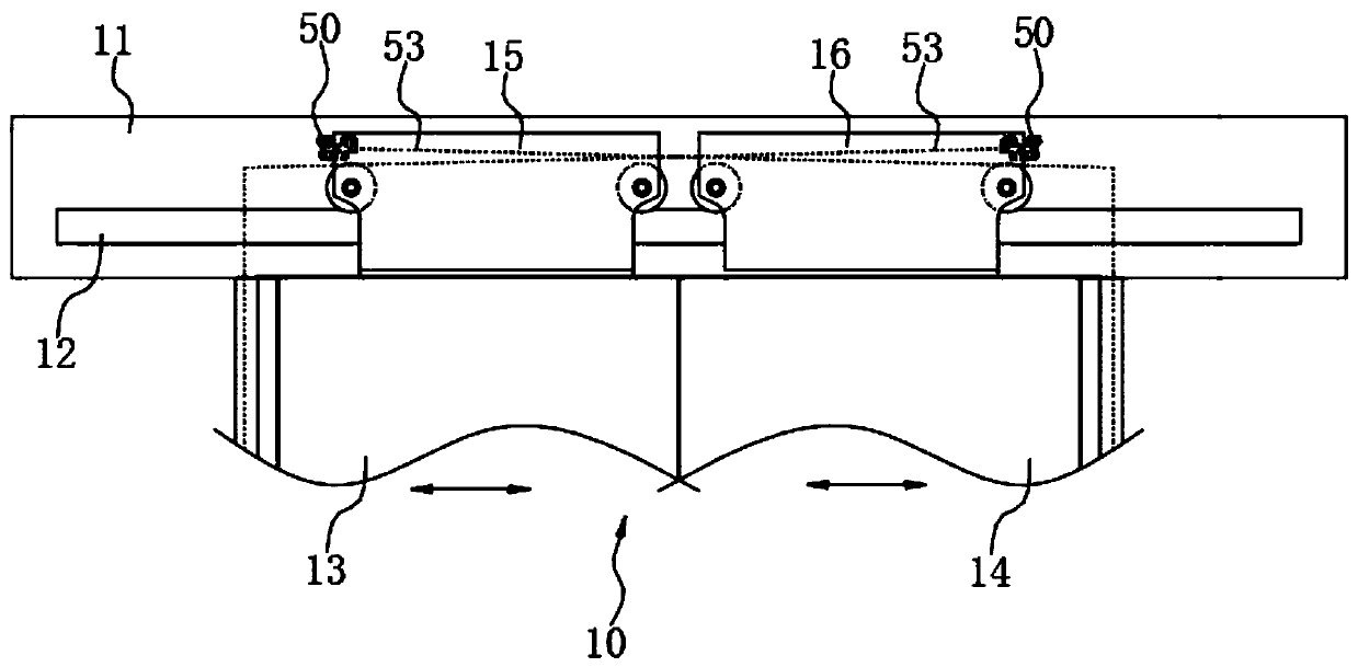
The invention relates to a pressure relief device and an elevator. The pressure relief device comprises a bearing mechanism, a traction mechanism and a pressure relief door mechanism, wherein the bearing mechanism comprises a driving assembly and a pressure relief carrier which are matched with each other; a pressure relief port is formed in the pressure relief carrier; the pressure relief port isused for communicating a hoistway and the outside of an elevator hall; the driving assembly is used for driving the traction mechanism to generate traction force; the pressure relief door mechanism is arranged on the pressure relief carrier and is matched with the opening and closing of the pressure relief port; and the pressure relief door mechanism is matched with the traction mechanism in a driving way. When the pressure relief port is opened, air current with a relatively large air pressure in the hoistway can be quickly discharged from the pressure relief port to the outside of the elevator hall, so that the difference between internal and external air pressures due to the chimney effect can be eliminated. Thus, an elevator hall door can be opened normally and smoothly in the absenceof the vertical pressure of air current in a hoistway direction; the required driving force is small; and the driving load and cost are lowered.

Description

technical field [0001] The invention relates to the technical field of elevator doors, in particular to a pressure relief device and an elevator. Background technique [0002] The chimney effect is common in high-rise buildings. The so-called chimney effect refers to the fact that the air in the elevator shaft flows upward from the bottom of the shaft and accumulates along the space of the shaft, causing the air pressure in the shaft to be greater than the air pressure outside the elevator hall, resulting in higher air pressure on the elevator hall door. Due to the large vertical air pressure, the opening is not smooth, or even cannot be opened normally; in addition, because the elevator hall door cannot be completely sealed when it is closed, the rising air will flow out from the matching gap of the elevator hall door door panel and generate wind noise. Noise can affect the comfort of passengers on the waiting elevator. In view of this, in the prior art, the method of incr...

Claims


Application Information

Patent Timeline
Patent Type & Authority Applications(China)
IPC IPC(8): B66B13/30B66B13/14B66B13/08
CPCB66B13/30B66B13/303B66B13/308B66B13/14B66B13/08
Inventor 梁昌龙区健聪梁宇杰李康松
Owner HITACHI ELEVATOR CHINA
Why Eureka
Try Eureka