Reinforcing structure for high-speed railway, roadbed assembly, roadbed system and construction method
A technology for strengthening structures and high-speed railways, which is applied in the field of roadbed components, roadbed systems and construction, and high-speed railway reinforcement structures. It can solve the problems of insufficient overall stability of the reinforced structure and instability of the roadbed, so as to improve the anti-sliding damage ability and reduce the foundation. Weakness, the effect of reducing bending and tensile stress
- Summary
- Abstract
- Description
- Claims
- Application Information
AI Technical Summary
Problems solved by technology
Method used
Image
Examples
Embodiment 1
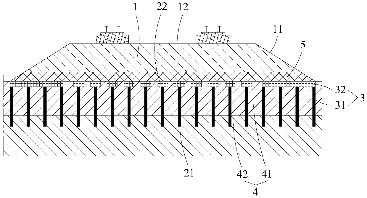
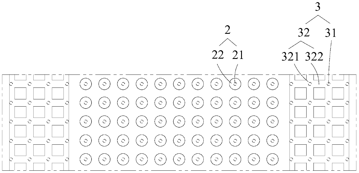
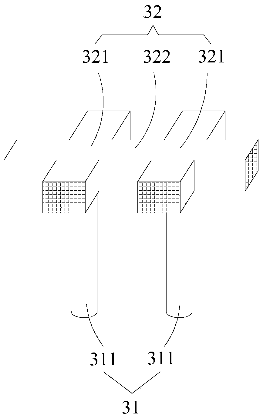
[0053] Such as figure 1 , 2 As shown in and 4, a reinforcement structure for high-speed railways includes a first reinforcement pile foundation assembly 2, and a second reinforcement pile foundation assembly 3 is respectively arranged on both sides of the first reinforcement pile foundation assembly 2. The second reinforcement pile foundation assembly 3 includes a first support pile part 31 and a support frame 32 rigidly connected with the first support pile part 31, the support frame 32 is arranged on the top of the first support pile part 31, and the support The frame 32 is an integral structure.
[0054] The first support pile 311 is preferably a CFG pile or a concrete pile or a reinforced concrete pile, and the compressive strength of the pile body test block is not less than 15MPa; the reinforced beam 322 is a reinforced concrete beam, and the concrete strength is not lower than C30; The beam 322 is rigidly connected to the adjacent reinforcement pile 3a.
[0055] The ...
Embodiment 2
[0066] Such as Figure 1-3 As shown, the reinforcement structure for high-speed railway described in this embodiment is different from Embodiment 1 in that the first reinforcement pile foundation assembly 2 includes several second support piles 21 arranged vertically at intervals , the top of the first reinforced pile foundation assembly 2 is rigidly connected with a pile cap 22, and the outer edge of the pile cap 22 protrudes from the side wall of the second support pile 21, at the top of the first reinforced pile foundation assembly 2 Rigidly connecting the pile cap 22 increases the load-bearing area of the first reinforced pile foundation assembly 2, fully exerts the load-bearing performance of the first reinforced pile foundation assembly 2, coordinates the proportion of the pile-soil bearing load, and improves the bearing capacity of the foundation.
[0067] On the basis of the above, in a further preferred manner, the second support piles 21 are arranged in a grid.
...
Embodiment 3
[0072] Such as figure 1 and 2 As shown, this embodiment discloses a subgrade assembly for high-speed railways, including a subgrade 1 with slopes 11 on both sides of the subgrade 1, and a reinforcing structure as described in embodiment 1 or 2 is arranged under the subgrade 1, The first reinforced pile foundation assembly 2 is arranged along the length direction of the roadbed 1, the second reinforced pile foundation assembly 3 is located on both sides of the first reinforced pile foundation assembly 2, at least a part of the second reinforced pile foundation The component 3 is located below the slope 11 .
[0073] Specifically, the thickness H of the reinforced cushion layer 2 is 400-600mm; the first tie bars in the cushion layer 5 can be arranged in one or more layers, and the ultimate tensile strength of the tie bars 2-a Greater than or equal to 80kN / m.
[0074] On the basis of the above, in a further preferred manner, a cushion layer 5 is also provided between the roadb...
PUM
 Abstract
Description
Claims
Application Information
 - R&D
- Intellectual Property
- Life Sciences
- Materials
- Tech Scout
- Unparalleled Data Quality
- Higher Quality Content
- 60% Fewer Hallucinations
Browse by: Latest US Patents, China's latest patents, Technical Efficacy Thesaurus, Application Domain, Technology Topic, Popular Technical Reports.
© 2025 PatSnap. All rights reserved.Legal|Privacy policy|Modern Slavery Act Transparency Statement|Sitemap|About US| Contact US: help@patsnap.com


