
Bridge deck suspended-type wind power generator and operation method

A technology for wind power generation devices and bridge decks, which is applied in the assembly of wind power engines, electromechanical devices, and wind power generation, and can solve the problems of fossil fuel environmental problems that cannot be solved, power consumption, and costly manpower and material resources, etc., to improve energy conversion. Efficiency, reduced friction, and low power transmission loss

Pending Publication Date: 2020-05-15
ZHEJIANG UNIVERSITY OF SCIENCE AND TECHNOLOGY
View PDF0 Cites 0 Cited by
  • Summary
  • Abstract
  • Description
  • Claims
  • Application Information

AI Technical Summary

Problems solved by technology

[0002] Fossil fuels are the main source of energy in the world today, but the environmental problems brought about by the massive use of fossil fuels have not been resolved. Therefore, it is imminent to find a new clean energy
In nature, wind energy is huge and ubiquitous, and it is an ideal clean energy source. However, the discovery of wind energy by humans has yet to be perfected. Most wind turbines can only be installed separately, requiring a large area of ​​open space, and usually a distance from There is a certain distance between users, and power needs to be transmitted at high voltage, which not only requires a lot of manpower and material resources, but also consumes power during transmission
If the power generation device can be effectively combined with the bridge, it will not only reduce the many shortcomings of long-distance power transmission, but also make wider use of wind energy. However, at present, there is no wind power generation device that can be effectively combined with the bridge. Effective combination to make more extensive use of wind energy has become a new topic and challenge

Method used


Image

  • Bridge deck suspended-type wind power generator and operation method
  • Bridge deck suspended-type wind power generator and operation method
  • Bridge deck suspended-type wind power generator and operation method

Examples


Embodiment Construction

[0022] The present invention will be further described below in conjunction with the accompanying drawings.

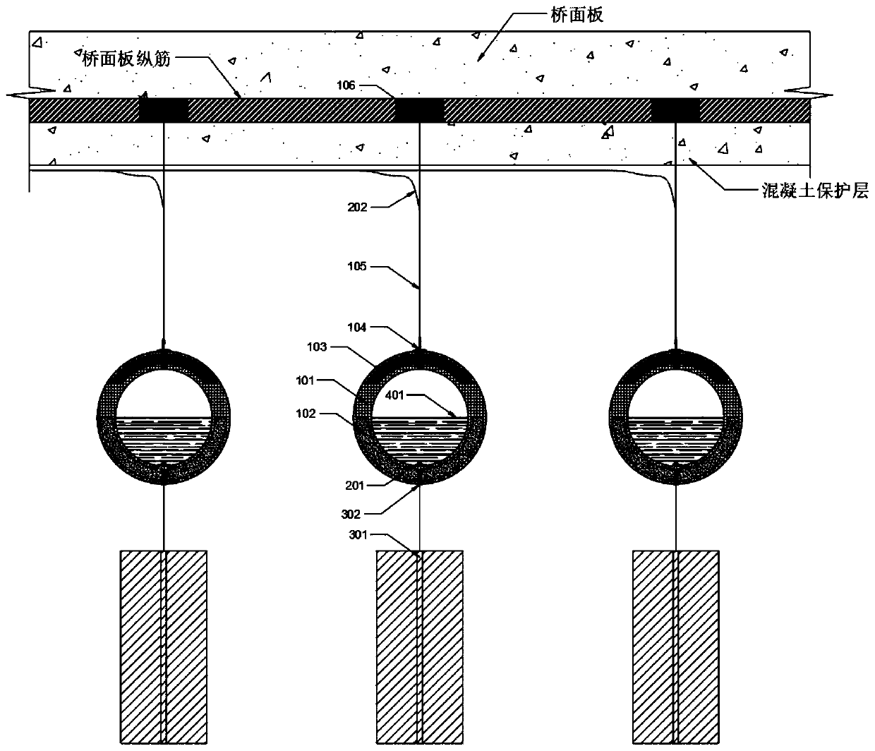
[0023] refer to Figure 1 ~ Figure 4 , a bridge deck suspension type wind power generation device, including a metal sheet 103, a magnet 102 and a magnetic fluid 401, the metal sheet 103 is the skeleton of the upper half of the rubber ball, the magnet 102 is the skeleton of the lower half of the rubber ball, the The metal sheet 103, the magnet 102 and the rubber ball 101 are molded together and wrapped in the rubber ball; two screw-shaped electrodes 201 are screwed into the reserved holes on the rubber ball 101 and the wire 202 is drawn out for use. Magnetic fluid 401 is arranged inside 101; the upper end of the rubber ball 101 is connected to the bridge deck through a steel wire 105, and the lower end of the rubber ball 101 is connected to the wind plate 301 through a steel wire.

[0024] Further, the high-strength screw 104 is screwed into the reserved hole on the t...


PUM


Abstract

The invention discloses a bridge deck suspended-type wind power generator which includes a metal sheet, a magnet and magnetic fluid. The metal sheet is a skeleton of the upper half part of a rubber ball, the magnet is a skeleton of the lower half part of the rubber ball, and the metal sheet and the magnet are cast-formed together with the rubber ball and wrapped in the rubber ball; two screw-shaped electrodes are screwed into preformed holes in the rubber ball and a wire is leaded out for use, and the rubber ball is internally provided with the magnetic fluid; and the upper end of the rubber ball is connected to a bridge deck through a steel wire, and the lower end of the rubber ball is connected with a windward plate through a steel wire. The invention further discloses an operation method of the bridge deck suspended-type wind power generator. The vibration energy in arbitrary direction can be absorbed and conversed into electrical energy, the power generation process is green and pollution-free, the power transmission loss is small, the power generation efficiency is high, and a building space is not occupied.

Description

technical field [0001] The invention relates to a suspended wind power generation device. The device relies on the bridge deck of a bridge. By connecting with the bridge deck, the device is suspended under the bridge deck, and the wind energy passing under the bridge is collected and converted to realize the conversion and utilization of wind energy. . Background technique [0002] Fossil fuels are the main energy sources in the world today, but the environmental problems brought about by the massive use of fossil fuels have not been resolved. Therefore, it is urgent to find a new clean energy source. In nature, wind energy is huge and ubiquitous, and it is an ideal clean energy source. However, the exploration of wind energy by humans has yet to be perfected. Most wind turbines can only be installed separately, requiring a large area of ​​open space, and usually a distance from There is a certain distance between users, and power needs to be transmitted at high voltage, wh...

Claims


Application Information

Patent Timeline
IPC IPC(8): F03D9/25F03D9/45F03D5/00F03D13/10E01D19/12E01D21/00H02K44/08H02K44/12H02K44/16
CPCF03D9/25F03D9/45F03D5/00F03D13/10E01D19/12E01D21/00H02K44/08H02K44/12H02K44/16Y02E10/70Y02E10/728Y02B10/30Y02E10/72
Inventor 罗战友李晓泉邹宝平朱剑锋陈永国赵昕陶燕丽陈其志丁康李超熊志强
Owner ZHEJIANG UNIVERSITY OF SCIENCE AND TECHNOLOGY
Learn More