Projectile base separation mass reduction extended-range projectile

A technology of projectile bottom and projectile, which is applied in the field of projectile bottom separation, mass reduction and range extension projectile, can solve the problem of reducing negative mass and extending range that has not been found, and achieves the effect of reducing negative mass, low use requirements and simple method

Pending Publication Date: 2020-05-15
ZHONGBEI UNIV
View PDF0 Cites 1 Cited by
  • Summary
  • Abstract
  • Description
  • Claims
  • Application Information

AI Technical Summary

Problems solved by technology

In order to pursue the terminal damage effect with a longer range, bottom row drag reduction and solid engine range extension are relatively common technical mean

Method used


Image

  • Projectile base separation mass reduction extended-range projectile
  • Projectile base separation mass reduction extended-range projectile
  • Projectile base separation mass reduction extended-range projectile

Examples


Embodiment 1

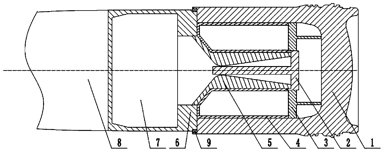
[0019] refer to figure 1 , the present embodiment provides a kind of ammunition with bottom separation, mass reduction and range extension, which includes warhead 8, solid motor and separation bottom mechanism in turn; The nozzle 5 of the product and the solid hair igniter 2; the solid motor cartridge 7 is arranged inside the solid motor housing 6 .

[0020] The separation bomb bottom mechanism includes a bomb bottom 1, a bottom row casing 4 and a bottom row igniter 3; the outlet of the nozzle 5 and the bottom row casing 4 are both arranged inside the bomb bottom 1; the bottom row casing 4 is arranged on the nozzle pipe 5 Between the bomb bottom 1. The inside of the bottom row housing 4 is provided with a charge column for containing propellant; one side of the solid motor housing 6 is fixedly connected to the combat part 8, and the other side of the solid motor housing 6 is sleeved on the inner side of the bullet bottom 1, and The bottom end of the solid motor housing 6 is ...

Embodiment 2

[0023] refer to figure 2 , the present embodiment provides a projectile shell with bottom separation, reduced mass and extended range. The difference between this embodiment and Embodiment 1 is that a bearing 9 is arranged between the solid motor casing 6 and the projectile bottom 1, and the bearing 9 is fixedly arranged on On the solid motor case 6. During the launch of the projectile, the separation bottom mechanism rotates at high speed, and the projectile and the separation bottom mechanism are connected by bearings. The radial force on the projectile is small, so the projectile rotates at a low speed due to inertia, which effectively reduces the impact of the projectile cannon. The mouth speed is conducive to the control of the projectile in the later stage.


PUM


Abstract

The invention discloses a projectile base separation mass reduction extended-range projectile. The projectile base separation mass reduction extended-range projectile comprises a warhead, a solid engine and a projectile base separation mechanism. The solid engine comprises a solid engine shell, a solid engine cartridge case, a spray tube used for spraying a combustion product and a fixed firing igniter. The solid engine cartridge case is arranged inside the solid engine shell. The projectile base separation mechanism comprises a projectile base, a base bleed shell and a base bleed igniter. According to the projectile base separation mass reduction extended-range projectile, the projectile base separation mechanism is separated from the projectile through fuel gas generated from base bleedpowder charge and solid engine powder charge, and the solid engine continues to propel the remaining effective load to fly; through the projectile base separation mechanism, the negative mass of the projectile in the flying process is effectively reduced, and the projectile flies much farther under the same powder charge condition. Through the projectile base separation design method, the negativemass of the projectile in the flying process is effectively reduced. Moreover, the method is simple and easy to realize. The projectile base separation mass reduction extended-range projectile has the advantages of being safe, reliable and low in using requirement.

Description

technical field [0001] The invention relates to the field of intermediate ballistics, in particular to a projectile with bottom separation, mass reduction and range extension. Background technique [0002] The main function of the bottom structure of the artillery projectile is to bear the high overload during launch, and to protect the damaged parts of the projectile from being damaged by high chamber pressure, so the structure is thicker; and the bottom of the projectile is generally equipped with a copper sealing belt , when the projectile flies, this part of the mass of the bottom of the projectile will become the negative mass that consumes the flight kinetic energy of the projectile. That is to say, the bottom of the projectile does not play any positive role in the flight process of the projectile after the projectile leaves the barrel. Instead, the weight of the projectile bottom reduces the flight speed of the projectile to a certain extent. In order to pursue the ...

Claims


Application Information

Patent Timeline
IPC IPC(8): F42B10/38F42B10/66
CPCF42B10/38F42B10/668
Inventor 赵晓尧陈智刚潘玉田王保国郭保全赵永娟
Owner ZHONGBEI UNIV
Why Eureka
Try Eureka