
Locally-inward-convex spinning shell of solid-propellant rocket engine

A solid rocket and engine technology, which is applied in the direction of rocket engine devices, machines/engines, mechanical equipment, etc., can solve the problems of low engine mass ratio, low raw material utilization rate, poor interchangeability of spinning shells, etc., to reduce local aerodynamics Heating degree, improvement of interchangeability and production efficiency, effect of high interchangeability and production efficiency

Inactive Publication Date: 2019-05-10
SHANGHAI XINLI POWER EQUIP RES INST
View PDF6 Cites 1 Cited by
  • Summary
  • Abstract
  • Description
  • Claims
  • Application Information

AI Technical Summary

Problems solved by technology

[0003] The spinning shell of the existing combustion chamber shell mainly adopts the structural form of constant thickness or convex variable thickness. Because the spinning shell of the constant thickness structure adopts the same wall thickness, there are large negative mass, low raw material utilization rate, and engine quality. Disadvantages such as low ratio; although the convex variable thickness structure has a certain improvement on the basis of the constant thickness structure, that is, the wall thickness of the spinning shell foundation is reduced, and only a certain thickness is convex along the axial direction at the welding part of the external parts. reinforcement, such as figure 1 shown
However, due to the difference in the position and quantity of the convex parts, it can only be produced by the positive spinning process with a limited processing length in a single process, and the interchangeability of the spinning shell is poor, and the production efficiency is low; at the same time, because the convex structure increases The diameter of the engine leads to increased aerodynamic resistance and severe local aerodynamic heating under the condition of high-speed flight of the missile, which is not conducive to further increasing the flight speed of the missile

Method used


Image

  • Locally-inward-convex spinning shell of solid-propellant rocket engine
  • Locally-inward-convex spinning shell of solid-propellant rocket engine

Examples


Embodiment Construction

[0018] The invention will be described in more detail hereinafter with reference to the accompanying drawings showing embodiments of the invention. However, this invention may be embodied in many different forms and should not be construed as limited to the embodiments set forth herein. Rather, these embodiments are provided so that this disclosure will be thorough and complete, and will fully convey the scope of the invention to those skilled in the art. In these drawings, the size and relative sizes of layers and regions may be exaggerated for clarity.

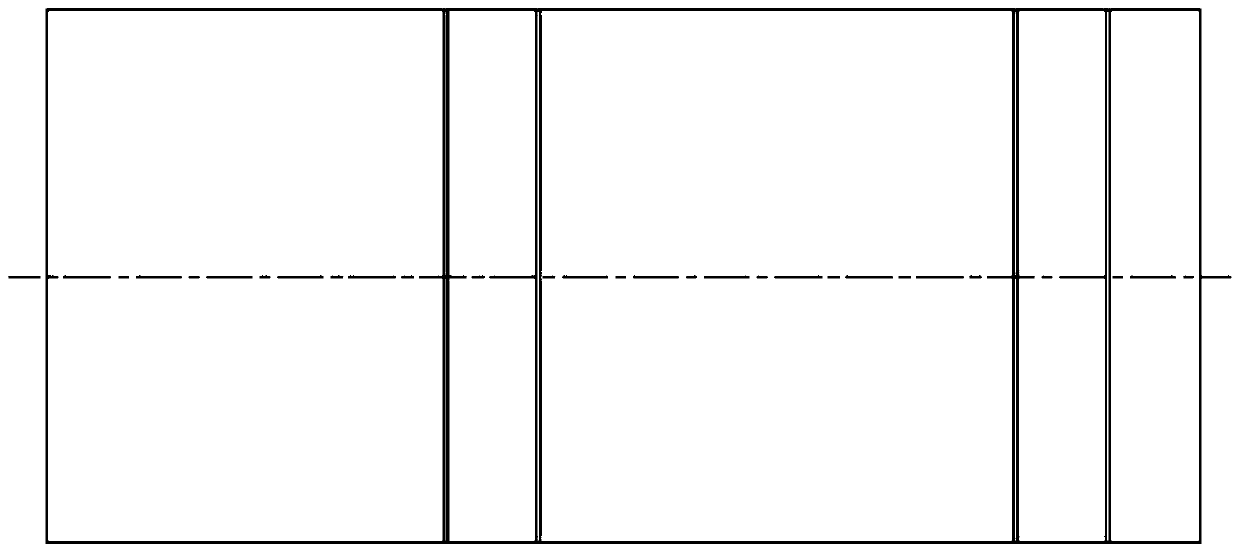
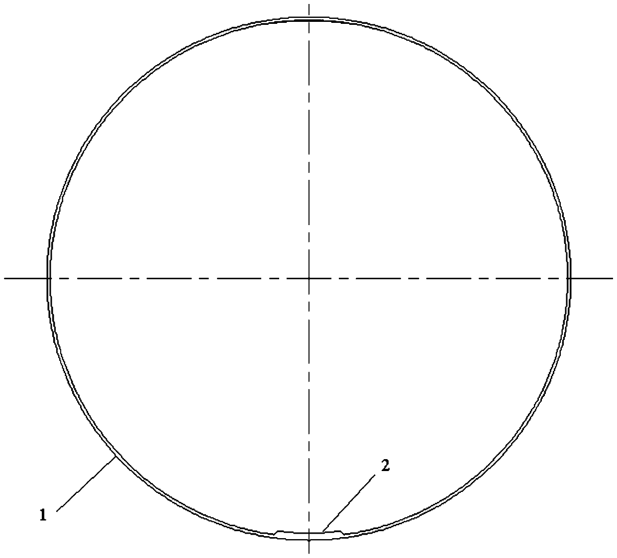
[0019] see figure 2 , taking the engine with a diameter of 300mm as an example, the structure design of the engine shell was carried out according to the coordination requirements of the mechanical interface issued by the missile. At the same time, considering factors such as process manufacturing, it is determined that the shell body is made of high-strength steel, and the total length of the shell body 1 is 2311mm, the ...


PUM


Abstract

The invention relates to a locally-inward-convex spinning shell of a solid-propellant rocket engine. The locally-inward-convex spinning shell of the solid-propellant rocket engine comprises a shell body, and an inner convex body is arranged on the inner side surface of the shell body. The shell body is of a tubular structure, the inner convex body penetrates through the shell body in the axial direction of the shell body, the thickness of the inner convex body is larger than the thickness of the shell body, and the inner convex body is connected with the shell body through inclined edges withthe same angles on the two sides. The locally-inward-convex spinning shell of the solid-propellant rocket engine can improve interchangeability and production efficiency of the spinning shell, reduceflight resistance and aerodynamic heating degree of a missile, increase flight speed of the missile, reduce negative quality of the engine and improve the mass ratio of the engine.

Description

technical field [0001] The invention relates to a component of a rocket motor, in particular to a partially inwardly convex solid rocket motor spinning casing. Background technique [0002] The combustion chamber casing is one of the important parts in the engine structure. It is a storage tank filled with solid propellant, a place where the propellant burns, and it is also a component of the missile body. Under the premise of satisfying the requirements of the engine development mission statement, in the design of the engine combustion chamber shell, the various load requirements during the flight test should be considered in the structural design, and the reliable connection of the front and rear compartments should be ensured to improve the reliability of the overall structure of the missile. sex. [0003] The spinning shell of the existing combustion chamber shell mainly adopts the structural form of constant thickness or convex variable thickness. Because the spinning ...

Claims


Application Information

Patent Timeline
Patent Type & Authority Applications(China)
IPC IPC(8): F02K9/34
Inventor 沈铁华乐浩罗静朱小兵赵亦东尹超薛牧遥陈树茂
Owner SHANGHAI XINLI POWER EQUIP RES INST
Learn More