
Extrusion type oxidizing agent supply solid-liquid mixing engine

A technology of solid-liquid mixing and oxidant, which is applied in the direction of machines/engines, rocket engine devices, mechanical equipment, etc., can solve the problems of increasing the negative mass of the engine, breaking through the aluminum sheet, and low combustion efficiency of the solid-liquid mixed engine, so as to reduce the negative mass , prevent leakage, and facilitate disassembly and assembly

Active Publication Date: 2022-04-12
NORTHWESTERN POLYTECHNICAL UNIV
View PDF9 Cites 0 Cited by
  • Summary
  • Abstract
  • Description
  • Claims
  • Application Information

AI Technical Summary

Problems solved by technology

[0005] The patent titled "Engine Head Structure, Solid-Liquid Mixed Rocket Engine and Rocket" published by Yu Nanjia of Beihang University and others, the application number of this invention is 201811172365.7, proposes an engine head cover, the swirl injector Connected to the bottom of the engine head cover, the engine head cover is connected to the combustion chamber shell flange, so that the combustion chamber communicates with the inner cavity of the swirl injector, and the oxidant swirl injection enters the combustion chamber, which effectively solves the problem of solid-liquid mixing The problem of low combustion efficiency of the engine, the engine head cover is connected with the flange of the engine combustion chamber shell to ensure flexible and detachable assembly, but the flange increases the negative mass of the engine
[0006] Wang Yin of Northwestern Polytechnical University and others published a patent titled "A Solid-liquid Hybrid Engine for Ground Vehicle Test". The application number of this invention is 201811375237.2. The nozzle is installed in the inner hole of the cover, and the front end cover and the pre-combustion chamber shell, the rear end cover and the supplementary combustion chamber shell are connected by threads, and the pre-combustion chamber shell and the supplementary combustion chamber shell of different lengths are replaced. Changing the size of the engine does not need to process the entire engine, which reduces the cost, but the threaded connection requires a certain thickness of the pre-combustion chamber shell and the after-combustion chamber shell, and the thickness of the combustion chamber shell needs to be increased, which increases the negative mass of the engine
[0007] Wang Yin of Northwestern Polytechnical University and others published a patent titled "A Solid-liquid Hybrid Engine for Ground Test Vehicle Experiment". The application number of this invention is 201811375237.2. In the front end cover, the connection between the front end cover and the oxidant delivery system is sealed by an aluminum sheet. When the engine is ignited, the ignition charge is ignited by the ignition element, and high-temperature and high-pressure gas is instantly generated to break through the aluminum sheet and enter the engine under the action of the oxidant. The combustion chamber ignites the powder column to realize the ignition of the engine. The igniter reduces the complexity of the engine ignition system, but the amount of high-temperature and high-pressure gas generated by the ignition powder is relatively small, and at the same time, the high-temperature and high-pressure gas will spontaneously flow towards the nozzle. The amount of gas flowing to the aluminum sheet is small, and there will be a phenomenon that the aluminum sheet cannot be broken through

Method used


Image

  • Extrusion type oxidizing agent supply solid-liquid mixing engine
  • Extrusion type oxidizing agent supply solid-liquid mixing engine
  • Extrusion type oxidizing agent supply solid-liquid mixing engine

Examples


Embodiment Construction

[0034] The embodiments described below by referring to the figures are exemplary and are intended to explain the present invention and should not be construed as limiting the present invention.

[0035] In describing the present invention, it should be understood that the terms "center", "longitudinal", "transverse", "length", "width", "thickness", "upper", "lower", "front", " Orientation indicated by rear, left, right, vertical, horizontal, top, bottom, inside, outside, clockwise, counterclockwise, etc. The positional relationship is based on the orientation or positional relationship shown in the drawings, which is only for the convenience of describing the present invention and simplifying the description, rather than indicating or implying that the referred device or element must have a specific orientation, be constructed and operated in a specific orientation, Therefore, it should not be construed as limiting the invention.

[0036] The invention relates to a solid-liqu...


PUM


Abstract

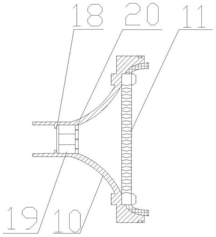
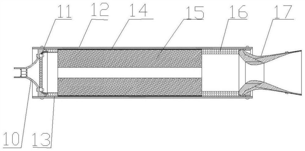
The invention discloses an extrusion type oxidizing agent supply solid-liquid mixing engine, and belongs to the technical field of aerospace propulsion. Comprising an extrusion gas cylinder, an oxidant storage box, an oxidant conveying pipeline and a combustion chamber, an outlet of the extrusion gas cylinder is communicated with an inlet of the oxidant storage tank through a pressure reducing valve and a flow regulating valve; an outlet of the oxidant storage tank is communicated with an inlet of the combustion chamber through an oxidant conveying pipeline; a multi-branch aluminum pipe inlet of the oxidant conveying pipeline is communicated with an outlet of the oxidant storage tank, a first outlet of the oxidant conveying pipeline is communicated with an inlet of the combustion chamber through a flow regulating valve and a pneumatic valve in sequence, and a second outlet of the oxidant conveying pipeline is communicated with the pneumatic valve through a pressure reducing valve and an electromagnetic valve in sequence; on-off of an oxidizing agent conveying system pipeline and two oxidizing agent filling modes are achieved through remote control; according to the invention, the injector and the spray pipe are fixed on the cabin wall of the combustion chamber by selecting a radial screw connection mode as a fixing mode, so that the combustion efficiency of the solid-liquid mixing engine is improved, and the negative quality caused by a flange plate is reduced.

Description

technical field [0001] The invention belongs to the field of aerospace propulsion technology, and in particular relates to a squeeze-type oxidant supply solid-liquid mixing engine. Background technique [0002] The solid-liquid hybrid engine is an aerospace power device that uses liquid oxidant and solid fuel as energy and working medium sources. It has the advantages of good safety, adjustable thrust, green environmental protection, and low cost. It is expected to be used in the aerospace field, especially in suborbital It has broad development space and application prospects in the fields of aircraft, small and medium-sized sounding rockets, missile weapons, and manned spacecraft. [0003] The oxidant supply system stably delivers oxidant to the thrust chamber at a specific pressure and flow rate during engine operation to ensure stable engine operation. Squeeze type oxidant supply system is composed of high-pressure gas cylinder, pressure reducing valve, oxidant storage ...

Claims


Application Information

Patent Timeline
Patent Type & Authority Applications(China)
IPC IPC(8): F02K9/72F02K9/95
CPCY02T10/30
Inventor 刘林林魏静姝胡松启
Owner NORTHWESTERN POLYTECHNICAL UNIV
Learn More