On-site checking device for current type on-line monitoring equipment and application method of on-site checking device

A technology of monitoring equipment and capacitive equipment, which is applied in the direction of measuring devices, measuring electrical variables, instruments, etc., can solve the problems of uncalibrated, low reliability, performance degradation, etc., to prevent and reduce power equipment failures, improve Accuracy and reliability, the effect of reducing weight and volume

Pending Publication Date: 2020-05-15
STATE GRID HUNAN ELECTRIC POWER +2
View PDF0 Cites 0 Cited by
  • Summary
  • Abstract
  • Description
  • Claims
  • Application Information

AI Technical Summary

Problems solved by technology

These online monitoring devices have many types and different quality levels, and they have been operated in outdoor high-temperature, high-humidity, and strong electromagnetic compatibility environments for a long time, often causing problems such as shortened lifespan, performance degradation, and low reliability.
[0003] At present, most of these online monitoring devices are only calibrated in the laboratory before they are put into operation, and cannot be calibrated after on-site operation. The main reasons are: (1) They need to be disassembled and sent to the laboratory for calibration due to power outages, which are often not performed due to power outage time constraints. Calibration; (2) There is no mature calibration device for on-site calibration

Method used


Image

  • On-site checking device for current type on-line monitoring equipment and application method of on-site checking device
  • On-site checking device for current type on-line monitoring equipment and application method of on-site checking device
  • On-site checking device for current type on-line monitoring equipment and application method of on-site checking device

Examples


Embodiment Construction

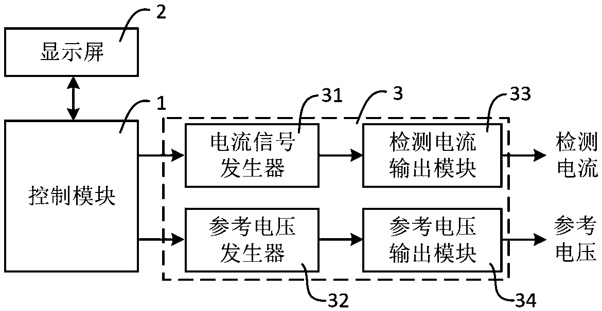
[0036] Such as figure 1 As shown, the on-site verification device for current-type on-line monitoring equipment in this embodiment includes a control module 1, an output module 2, and a multifunctional voltage and current signal generator 3, and the multifunctional voltage and current signal generator 3 includes a current signal generator 31, a reference Voltage generator 32, detection current output module 33 and reference voltage output module 34, control module 1 is connected with output module 2, current signal generator 31, reference voltage generator 32 respectively, the output terminal of current signal generator 31 and detection current The output module 33 is connected, and the output terminal of the reference voltage generator 32 is connected to the reference voltage output module 34 .

[0037] In this embodiment, the control module 1 is used to control the working state of the current signal generator 31 and the reference voltage generator 32, for example, to adjust...


PUM


Abstract

The invention discloses an on-site checking device for current type on-line monitoring equipment and an application method of the on-site checking device. The device comprises a control module, an output module and a multifunctional voltage and current signal generator, wherein the multifunctional voltage and current signal generator comprises a current signal generator, a reference voltage generator, a detection current output module and a reference voltage output module, the control module is respectively connected with the output module, the current signal generator and the reference voltage generator, the output end of the current signal generator is connected with the detection current output module, and the output end of the reference voltage generator is connected with the referencevoltage output module. The application method is used for on-site checking of various current type on-line monitoring equipment. According to the invention, on-site checking of various current type on-line monitoring equipment can be realized, the size and weight of the equipment can be effectively reduced, one set of instrument wiring can be shared, on-site checking is rapid and convenient, andon-site checking results can be conveniently obtained according to detection equipment data.

Description

technical field [0001] The invention relates to the field of on-line monitoring of electric power equipment, in particular to an on-site checking device for current-type on-line monitoring equipment and an application method thereof. Background technique [0002] With the construction of the ubiquitous electric power Internet, a large number of online monitoring devices are currently installed in substations, such as online monitoring of lightning arrester leakage current, online monitoring of transformer iron core clip current, online monitoring of capacitive current of capacitive equipment, and online monitoring of high-frequency current, etc. . These online monitoring devices have many types and different quality levels, and they have been operated in outdoor high temperature, high humidity, and strong electromagnetic compatibility environments for a long time, often causing problems such as shortened life, reduced performance, and low reliability. [0003] At present, m...

Claims


Application Information

Patent Timeline
Patent Type & Authority Applications(China)
IPC IPC(8): G01R35/00
CPCG01R35/005
Inventor 赵世华李欣刘赟孙利朋万勋叶会生黄海波
Owner STATE GRID HUNAN ELECTRIC POWER
Why Eureka
Try Eureka