
Light transmission bandwidth tracking method and system

A tracking system and bandwidth technology, applied in the field of laser ranging, can solve the problems of central wavelength temperature drift error, manufacturing tolerance, etc.

Pending Publication Date: 2020-05-15
深圳市合力泰光电有限公司
View PDF0 Cites 0 Cited by
  • Summary
  • Abstract
  • Description
  • Claims
  • Application Information

AI Technical Summary

Problems solved by technology

[0005] However, in actual use, due to the batch consistency difference of the VCSEL laser light source, the center wavelength temperature drift error when the laser light source is working, and the coating manufacturing tolerance of the narrow-band filter, the narrow-band filter is actually used in actual use. The bandwidth of the light sheet is usually 5-10 times larger than the luminous bandwidth of the laser light source to ensure that the laser light source can be reliably received by the TOF camera, and even this still leads to the signal-to-noise ratio that the TOF camera can obtain compared with the ideal signal-to-noise 3dB-5dB lower than

Method used


Image

  • Light transmission bandwidth tracking method and system
  • Light transmission bandwidth tracking method and system
  • Light transmission bandwidth tracking method and system

Examples


Embodiment

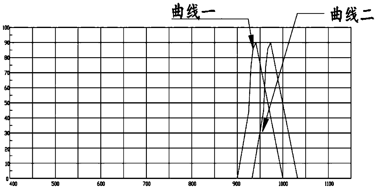
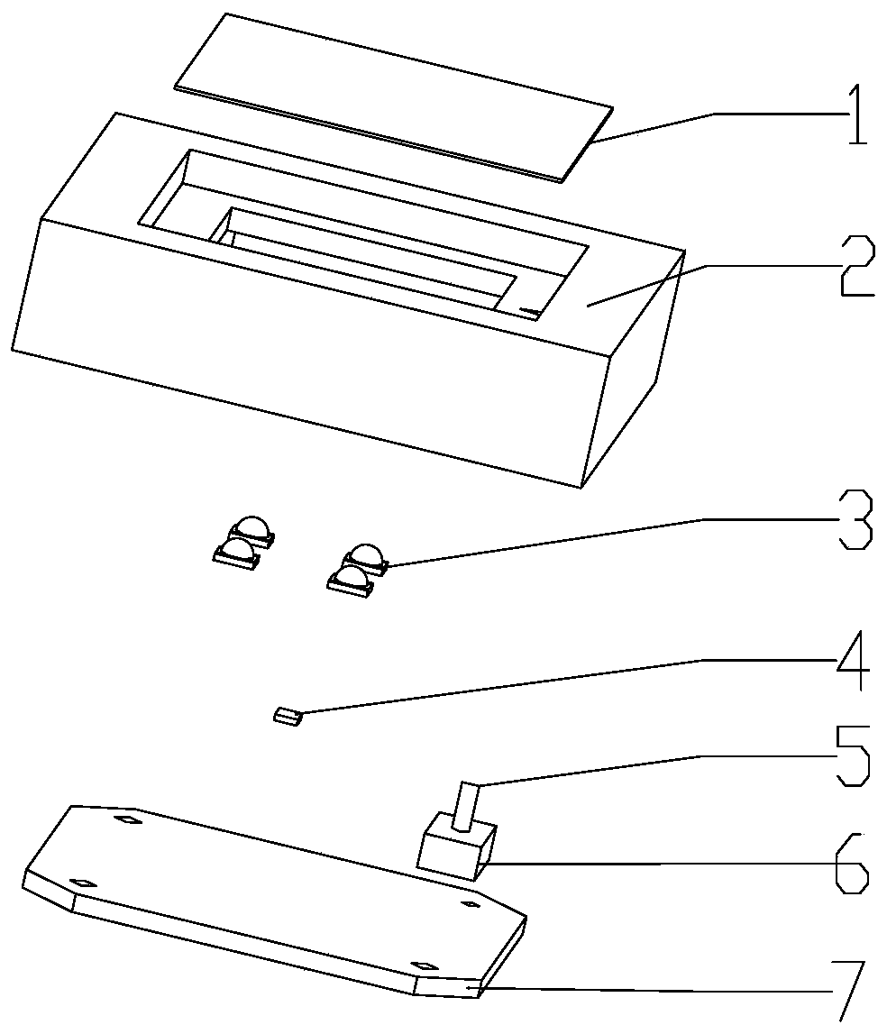
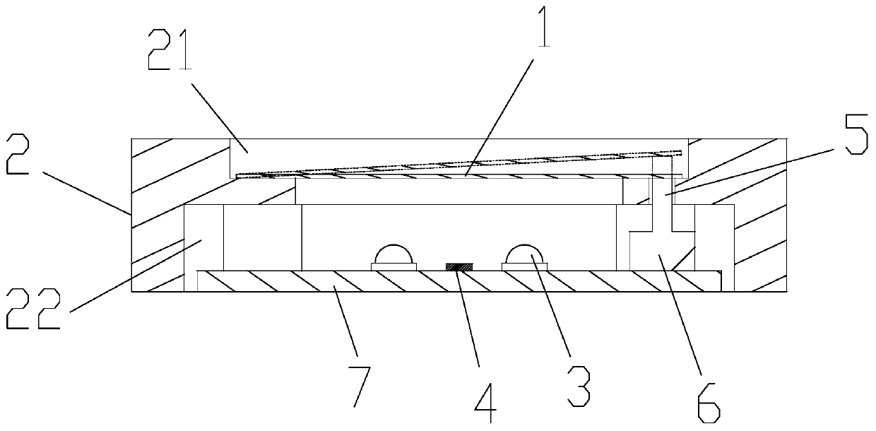
[0052] Please refer to attached Figure 1-5 As shown, the embodiment of the present invention discloses a method for tracking the passband bandwidth, the method comprising: emitting incident light onto the first optical filter 1, and simultaneously detecting the reflected light intensity on the first optical filter 1; The outgoing light on a filter 1 is reflected to the second filter 8 through the measured object; by adjusting the angle of the first filter 1 to change the incident angle of the incident light on the first filter 1, the second filter is obtained. The peak value and the valley value of the reflected light intensity on a filter 1; Adjust the angle of the second filter 8 according to the angle adjusted by the first filter 1 during the valley; the first filter The sheet 1 is fixed at the angle corresponding to the valley value, and the second filter 8 is fixed at the adjusted angle to obtain a good incident light effect on the second filter 8 .

[0053] The first o...


PUM


Abstract

The invention discloses a light transmission bandwidth tracking method and system, and the method comprises the steps: transmitting incident light to a first optical filter, and detecting the intensity of reflected light on the first optical filter; reflecting the emergent light on the first optical filter to the second optical filter through the measured object; changing the incident angle of incident light on the first optical filter by adjusting the angle of the first optical filter, and obtaining the peak value and the valley value of the intensity of reflected light on the first optical filter; adjusting the angle of the second optical filter according to the adjustment angle corresponding to the first optical filter at the valley value; and fixing the first optical filter at the angle corresponding to the valley value, fixing the second optical filter at the adjusted angle, and obtaining a good incident light effect on the second optical filter. The method and the system providedby the invention are used for the TOF camera, and can greatly reduce the light transmission bandwidth of the narrow-band optical filter of the TOF camera, so that the TOF camera obtains a better image signal-to-noise ratio.

Description

technical field [0001] The invention discloses a method and a system for tracking the optical bandwidth, and belongs to the technical field of laser ranging. Background technique [0002] TOF: Time Of Flight, the time-of-flight ranging method, its principle is to measure the distance by shining light on the target object and measuring the transmission time of the light between the lens and the object. [0003] VCSEL: Vertical Cavity Surface Emitting Laser, a vertical cavity surface emitting laser, used to emit a laser beam. [0004] In the TOF ranging system, the TOF camera measures the point cloud 3D data of the measured space by measuring the reflection time of the light source after the synchronously triggered pulse light source is irradiated into the measured space. In order to ensure that the TOF camera has a good enough signal during the measurement process The noise ratio (SNR) requires the optical system to minimize the intensity of the invalid ambient background li...

Claims


Application Information

Patent Timeline
IPC IPC(8): G01S7/481G01S17/14G02B7/00G03B17/12
CPCG01S7/4811G02B7/006G03B17/12
Inventor 陈明王家财
Owner 深圳市合力泰光电有限公司
Learn More