
Motor integrated type main speed reducer assembly

A main reducer, integrated technology, applied in the direction of electrical components, electromechanical devices, mechanical equipment, etc., can solve the problems of poor overall rigidity, unfavorable vehicle performance, etc., to reduce the impact of rigidity, improve rigidity, and increase contact area Effect

Inactive Publication Date: 2020-05-15
青岛汽车零部件科技创新服务有限公司
View PDF0 Cites 0 Cited by
  • Summary
  • Abstract
  • Description
  • Claims
  • Application Information

AI Technical Summary

Problems solved by technology

[0003] Since the motor is connected to the wheel reducer through bolts, although the structure is simple, the overall rigidity is poor, which is not conducive to the improvement of vehicle performance.

Method used


Image

  • Motor integrated type main speed reducer assembly
  • Motor integrated type main speed reducer assembly
  • Motor integrated type main speed reducer assembly

Examples


Embodiment Construction

[0038] The following will clearly and completely describe the technical solutions in the embodiments of the present invention with reference to the accompanying drawings in the embodiments of the present invention. Obviously, the described embodiments are only some, not all, embodiments of the present invention. Based on the embodiments of the present invention, all other embodiments obtained by persons of ordinary skill in the art without creative efforts fall within the protection scope of the present invention.

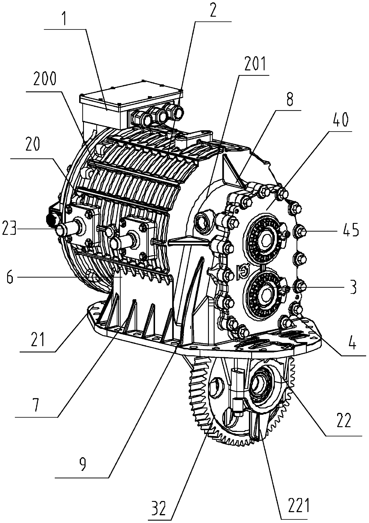
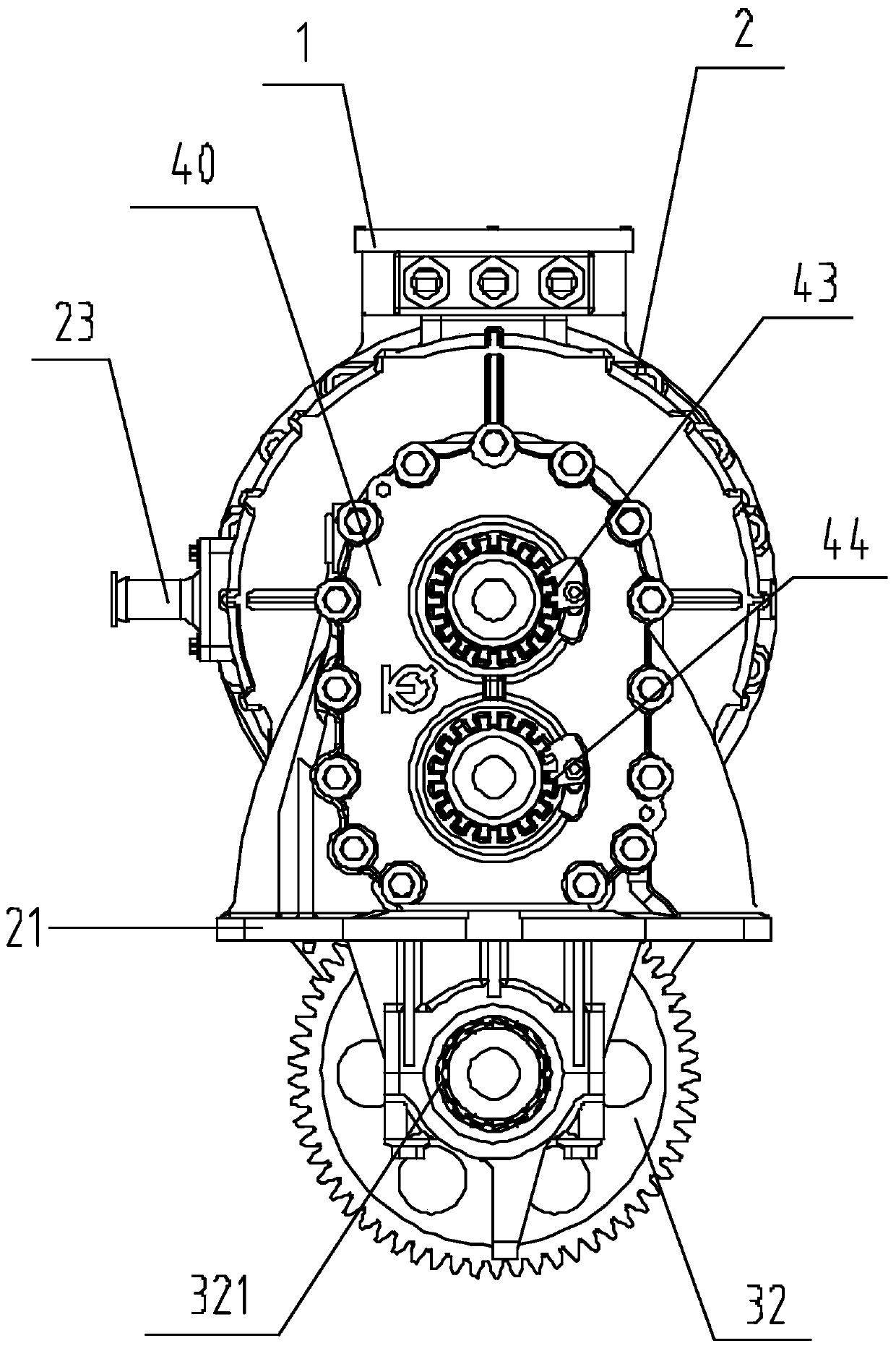
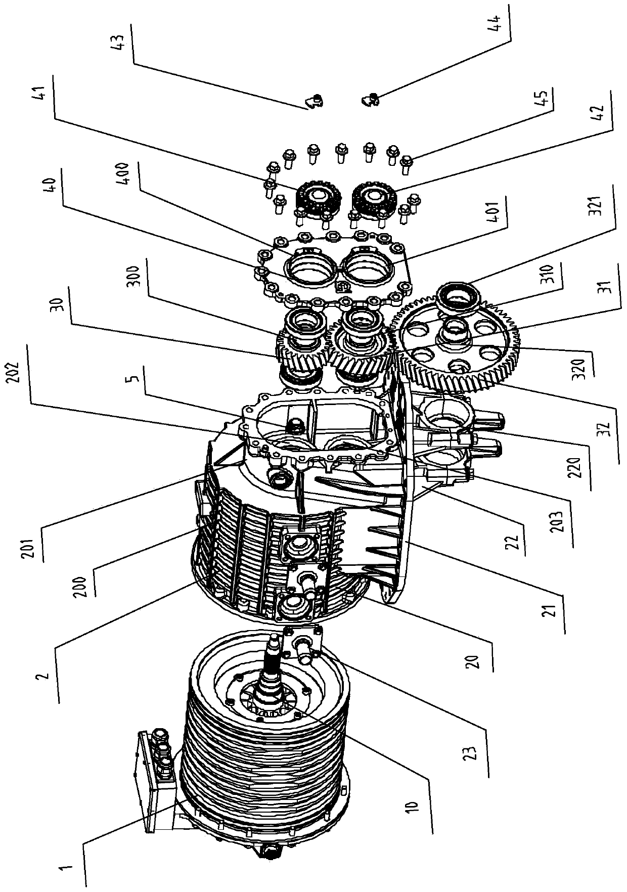
[0039] according to Figure 1 to Figure 4 As shown, a motor-integrated final reducer assembly includes a drive motor 1 , a transmission mechanism 3 , a final reducer housing 2 and a fixing mechanism 4 .

[0040] The right end of the driving motor 1 is provided with a motor shaft 10, and the motor shaft 10 is used to drive the transmission mechanism 3 to rotate.

[0041] The transmission mechanism 3 adopts a cylindrical helical gear train, and the transmission mech...


PUM


Abstract

The invention provides a motor integrated type main speed reducer assembly. The assembly comprises a driving motor, a transmission mechanism, a main speed reducer shell and a fixing mechanism, a motorshaft is arranged at the right end of the driving motor; the transmission mechanism comprises a first runner, a second runner and a third runner; the motor shaft drives the first runner to rotate; the second runner is arranged at the bottom of the first runner; the second runner is meshed with the first runner; the third runner is arranged at the bottom of the second runner; the third runner is meshed with the second runner; the main speed reducer shell is in interference fit with the driving motor; the main speed reducer shell is connected with the transmission mechanism through a bearing; the fixing mechanism comprises an end cover, an adjusting ring and a locking plate; the end cover is fixedly connected with the main speed reducer shell through the fixing bolt, one end of the adjusting ring is in threaded connection with the transmission mechanism, the other end of the adjusting ring is fixedly connected with the end cover through the locking piece, and therefore assembly has theadvantages that the overall rigidity can be improved, and the performance of the whole vehicle can be improved.

Description

technical field [0001] The invention belongs to the technical field of distributed drive electric drive axles, in particular to a motor-integrated final reducer assembly. Background technique [0002] With the further advancement of new energy vehicle technology in recent years, the technology of new energy vehicles has become more and more perfect, and the application of electric drive axles has become more and more, so the technical upgrade of electric drive axles has become more important. At present, the mainstream layout structure at home and abroad is that the motor is connected to the wheel reducer through bolts, and is used to drive the wheel reducer through the motor. [0003] Since the motor is connected to the wheel-side reducer through bolts, although the structure is simple, the overall rigidity is poor, which is not conducive to the improvement of vehicle performance. Contents of the invention [0004] The present invention proposes a motor-integrated main r...

Claims


Application Information

Patent Timeline
Patent Type & Authority Applications(China)
IPC IPC(8): H02K7/116F16H57/023F16H57/04
CPCF16H57/023F16H57/0413F16H2057/02043F16H2057/02086F16H2057/02091F16H2057/02095H02K7/116
Inventor 纪建奕韩振东杨朝会刘本友刘宗强王至昊
Owner 青岛汽车零部件科技创新服务有限公司
Learn More