Rotary crushing machine

A shredder and rotary technology, applied in the field of waste treatment equipment, can solve the problem of reducing the contact surface

Pending Publication Date: 2020-05-19
艾芦精密机械(江苏)有限公司
View PDF0 Cites 0 Cited by
  • Summary
  • Abstract
  • Description
  • Claims
  • Application Information

AI Technical Summary

Problems solved by technology

[0004] In view of the above-mentioned problems in the prior art, it is now intended to provide a rotary pulverizer, which divides the knife-edge end of the pulverizing blade into two parts, and the knife-edge ends of the separated two parts are staggered back and forth, which not only reduces the The contact surface with the object to be crushed improves the crushing efficiency, and also doubles the number of cutter heads of the crushing blade, which improves the crushing effect; in addition, the upper part of the crushing shell and located at the rear of the crushing drum in the direction of rotation is provided with a The small parts recovery port enables the small parts to be thrown to the recovery port through its centrifugal action during the rotation of the crushing drum, thereby realizing the separation of small parts, avoiding the mixing of small parts and crushed debris, and reducing the need for the crushing drum to crush small parts In addition, a flywheel disc is provided at the end of the rotating shaft away from the driving turntable, and the flywheel disc and the driving turntable are symmetrically arranged at both ends of the rotating shaft, and are also arranged symmetrically about the crushing drum, so that the two ends of the crushing drum Consistent force, preventing the shaft from bending due to uneven force after long-term use, prolonging the service life of the pulverizer

Method used


Image

  • Rotary crushing machine
  • Rotary crushing machine
  • Rotary crushing machine

Examples


Embodiment Construction

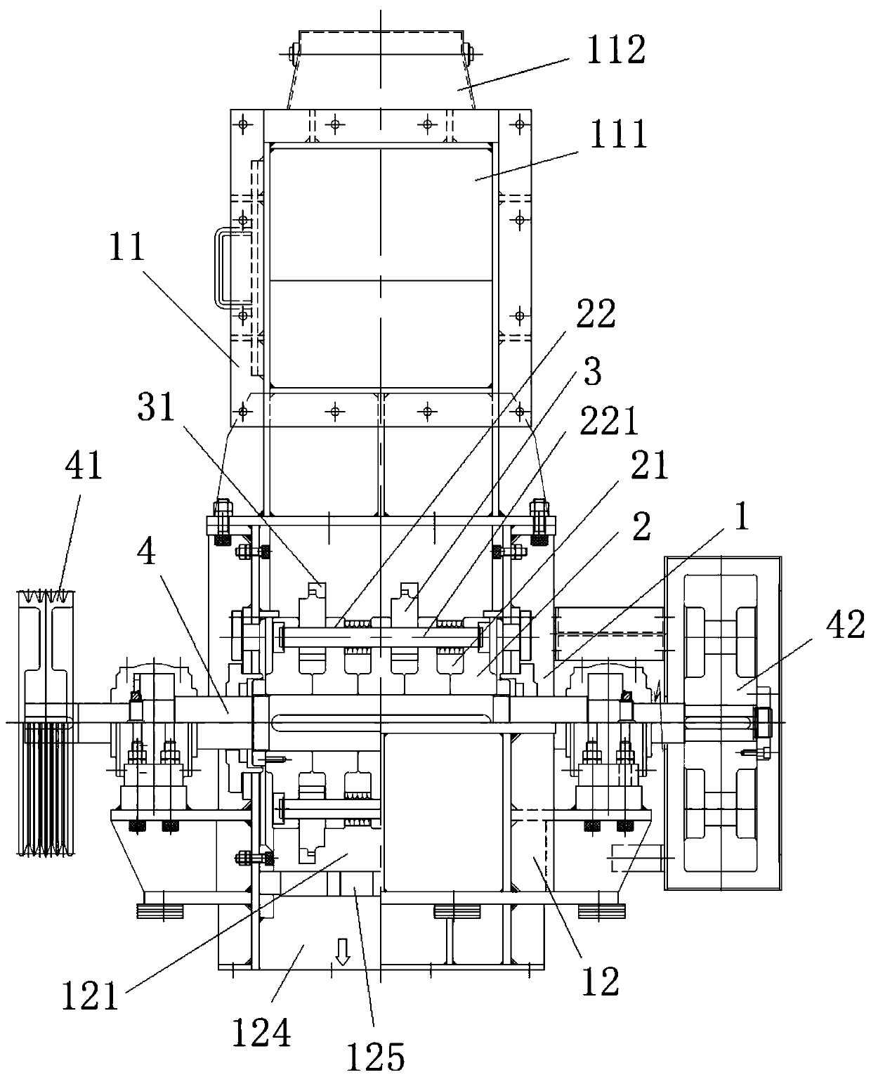
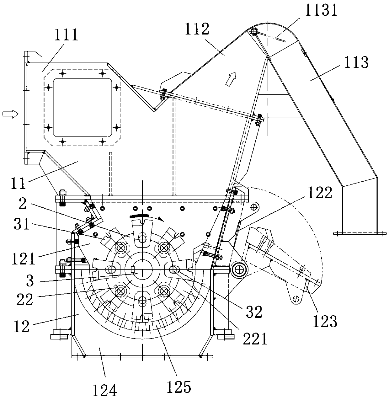
[0025] In order to make it easy to understand the technical means, creative features, goals and effects achieved by the present invention, the following examples are combined with the appended figure 1 to attach figure 2 The technical solutions provided by the present invention are described in detail, but the following content is not intended as a limitation of the present invention.

[0026] figure 1 It is a structural diagram of an embodiment of a rotary pulverizer of the present invention; figure 2 It is a structural diagram of another perspective of a preferred embodiment of the present invention. like figure 1 and figure 2 As shown, the rotary pulverizer provided in this embodiment includes: a pulverizing shell 1, a pulverizing drum 2, a pulverizing blade 3 and a rotating shaft 4, a pulverizing drum 2 is arranged in the pulverizing housing 1, and a pulverizing blade is arranged on the pulverizing drum 2 3. At the same time, the crushing drum 2 is fixed on the rot...


PUM


Abstract

The invention provides a rotary crushing machine, and belongs to the technical field of waste treatment equipment. The rotary crushing machine comprises a crushing shell, a crushing roller, crushing cutter blades and a rotating shaft. According to the rotary crushing machine, a small part recycling opening is formed in the crushing shell, and directly recyclable small parts on an object to be crushed can be recycled separately, so that the small parts are prevented from mixing into crushed scraps, and the crushing burden brought by crushing the small parts is also reduced; in addition, cutterhead ends of the crushing cutter blades are divided into two parts which are distributed in a staggered manner back and forth, the contact area between the cutter head ends and the object to be crushed is effectively reduced, and the doubling of the cutter heads of the crushing cutter blades can also be realized, so that the crushing efficiency is improved, and the crushing effect is ensured; moreover, symmetrical distribution of the structures at two ends of the rotating shaft is realized by respectively arranging a driving turntable and a flywheel disc at the two ends of the rotating shaft,so that the stress uniformity of the crushing roller and the rotating shaft is ensured; and therefore, the problem of deformation caused by non-uniform stress is avoided, the crushing effect is ensured, and the service life of the crushing machine is prolonged.

Description

technical field [0001] The invention relates to the technical field of waste treatment equipment, in particular to a rotary pulverizer. Background technique [0002] In the process of waste recycling, some recyclable waste needs to be shredded before it can be recycled better. Therefore, these recyclable wastes need to be put into a shredder for shredding. [0003] However, in the existing pulverizers, the contact surface between the pulverizing blade and the object to be pulverized is relatively large, resulting in the problem of low pulverizing efficiency. In addition, the number of pulverizing blades on the same pulverizing drum is small, which also leads to low pulverizing efficiency. The problem of poor crushing effect. Moreover, the existing pulverizer lacks separation operation, and it is difficult to separate small parts that can be directly recovered, such as screws on the object to be pulverized. burden. In addition, one end of the rotating shaft of the existing...

Claims


Application Information

Patent Timeline
IPC IPC(8): B02C18/14B02C18/22B02C18/18B02C18/24
CPCB02C18/0084B02C18/14B02C18/18B02C18/2216B02C18/2225B02C18/24B02C2201/06
Inventor 岡田泰元
Owner 艾芦精密机械(江苏)有限公司
Why Eureka
Try Eureka