Locking mechanism and bending die quick clamping system including locking mechanism

A locking mechanism and clamping technology, which is applied in the direction of forming tools, manufacturing tools, metal processing equipment, etc., can solve the problems of high mold precision requirements for segmented molds and loose clamping of segmented molds, so as to eliminate safety problems , The clamping force does not attenuate, and the effect of avoiding torsional deformation

Pending Publication Date: 2020-05-19
王勇
View PDF0 Cites 4 Cited by
  • Summary
  • Abstract
  • Description
  • Claims
  • Application Information

AI Technical Summary

Problems solved by technology

[0006] In order to solve the technical problem that the clamping mechanism in the prior art cannot realize the independent control of the segmented mold, the precision of the segmented mold is required to be high, or it is easy to cause the clamping of some segmented molds not to be tight, the present invention provides a The locking mechanism and the quick clamping system of the bending die containing it can solve the above problems

Method used


Image

  • Locking mechanism and bending die quick clamping system including locking mechanism
  • Locking mechanism and bending die quick clamping system including locking mechanism
  • Locking mechanism and bending die quick clamping system including locking mechanism

Examples


Embodiment 1

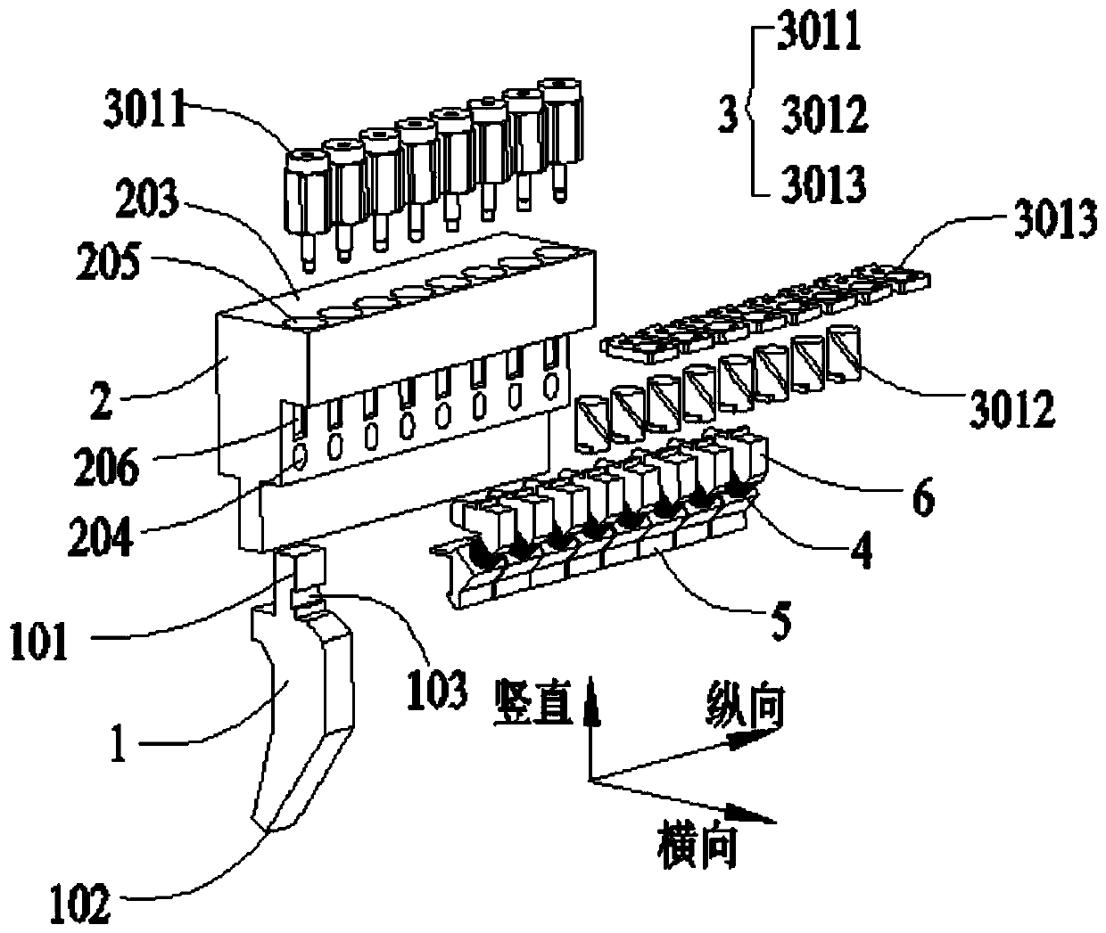
[0075] Embodiment 1, a locking mechanism, such as figure 1 , Figure 13-Figure 15 As shown, it includes an installation base 2 and a clamping executive assembly. One or more groups of clamping executive assemblies are arranged longitudinally on one or both sides of the installation base 2, and the mold is clamped to the clamping executive assembly. Between the installation base 2, the clamping execution assembly approaches or moves away from the installation base 2 along a plane perpendicular to the longitudinal direction; and, adjacent to the clamping execution assembly is arranged closely.

[0076] The installation base 2 is a fixed part, and the installation base 2 is fixed on the bending machine. The movement direction of the clamping actuator assembly is perpendicular to its arrangement direction, so when the clamping actuator assembly clamps the mold, the adjacent clamp There will be no interference between the clamping actuators, and the distance between the adjacent c...

Embodiment 2

[0082] Embodiment 2, on the basis of Embodiment 1, the locking actuator assembly further includes an elastic body 4 located between the anti-drop locking hook 5 and the locking tooth 6; the elastic member 4 is suitable for squeezing the anti-drop locking hook 5 , and apply a force towards the vertical reference plane 202 to the clamping part 101 of the upper mold through the anti-drop lock hook 5, the force can be the total force or a component force, that is, the direction of the elastic force of the elastic member 4 can be directly opposite to the vertical The direction of the straight reference plane 202 may also extend obliquely to the direction of the vertical reference plane 202 .

[0083] The force exerted by the third working surface 502 of the anti-drop lock hook 5 on the upper mold 1 is vertically upward for supporting the upper mold 1, and the third working surface 502 and the horizontal reference plane 201 jointly limit the displacement of the upper mold 1 in the ve...

Embodiment 2a

[0087] Embodiment 2a is used for an asymmetric mold, and the fourth working surface 604 is a circular curved surface. Such as Figure 16 As shown, the matching structure between the anti-drop lock hook 5 and the locking tooth 6 is: the bottom of the locking tooth 6 extends obliquely downward with a positioning column 603, and the fourth working surface 604 is the circumferential surface of the positioning column 603, away from the upper One end of the anti-drop locking hook 5 of the clamping part 101 is provided with a positioning groove 503 coupled with the positioning post 603 , and the elastic member 4 is sheathed on the circumferential surface of the positioning post 603 . The positioning column 603 extends toward the installation base 2 .

[0088] The structure on one side of the anti-drop locking hook 5 that cooperates with the upper mold 1 is as follows: a protruding hook 501 facing the direction of the installation base 2 is provided at the bottom of the second workin...


PUM


Abstract

The invention discloses a locking mechanism and a bending die quick clamping system including the locking mechanism. The locking mechanism comprises a mounting base and one set or more sets of clamping execution assemblies, the one set or more sets of clamping execution assemblies arranged in the longitudinal direction are provided on the one transverse side or two transverse sides of the mountingbase, a mold is clamped between the clamping execution assemblies and the mounting base, and the clamping execution assemblies are close to or away from the mounting base in a plane perpendicular tothe longitudinal direction; and the adjacent clamping execution assemblies are arranged next to each other. The locking mechanism and the bending die quick clamping system including the locking mechanism can completely eliminate the situation that the mold cannot be completely clamped when the clamping position slightly changes due to mold machining errors or mold abrasion and other reasons (potential safety hazards can occur), it is guaranteed that any segment of the mold at the any mounting position on the mounting base is uniformly and consistently clamped, and the clamping force is not degraded.

Description

technical field [0001] The invention relates to the field of clamping of bending dies, in particular to a locking mechanism and a quick clamping system of bending dies including the locking mechanism. Background technique [0002] In the workpiece bending process, it is usually necessary to use a bending upper mold (referred to as an upper mold in this application) and a bending lower mold. The bending upper mold has an upper mold clamping part and an upper mold cutter head, and the bending lower mold is V type, the workpiece is placed between the bending upper die and the bending lower die, the clamping part of the upper die is clamped on the bending machine, and the upper die cutter head exerts force on the surface of the workpiece to bend the workpiece. [0003] According to the relative position of the upper die cutter head and the center line of the clamping part of the upper die, there are two types of bending upper dies: the head symmetrical type and the head asymmetr...

Claims


Application Information

Patent Timeline
Patent Type & Authority Applications(China)
IPC IPC(8): B21D37/10B21D37/04B21D55/00
CPCB21D37/10B21D37/04B21D55/00B30B15/026
Inventor 王勇林艳
Owner 王勇
Why Eureka
Try Eureka