
Locking platform and machine tool system

A platform and compression plate technology, which is applied to metal processing machinery parts, large fixed members, metal processing equipment, etc., can solve problems such as danger, pallet and worktable cannot maintain a fixed connection state, and pallets move away from the workbench, etc. , to achieve the effect of convenient combination, easy maintenance and replacement, and short stroke

Pending Publication Date: 2020-05-19
北京优备加科技有限公司
View PDF0 Cites 1 Cited by
  • Summary
  • Abstract
  • Description
  • Claims
  • Application Information

AI Technical Summary

Problems solved by technology

Since the existing technology uses pneumatic or electric structures to fix the pallet and the worktable, when encountering power failure or gas failure, the pallet and the workbench cannot maintain a fixed connection state, and at this time the pallet may be stressed. Causing the pallet to move off the table, creating a hazard

Method used


Image

  • Locking platform and machine tool system
  • Locking platform and machine tool system
  • Locking platform and machine tool system

Examples


Embodiment 1

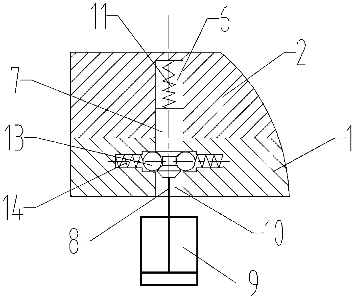
[0032] The locking platform in this embodiment, such as figure 1 with figure 2 As shown, it includes a pressing plate 1 , a tray 2 , an abutting assembly and an unlocking assembly 9 .

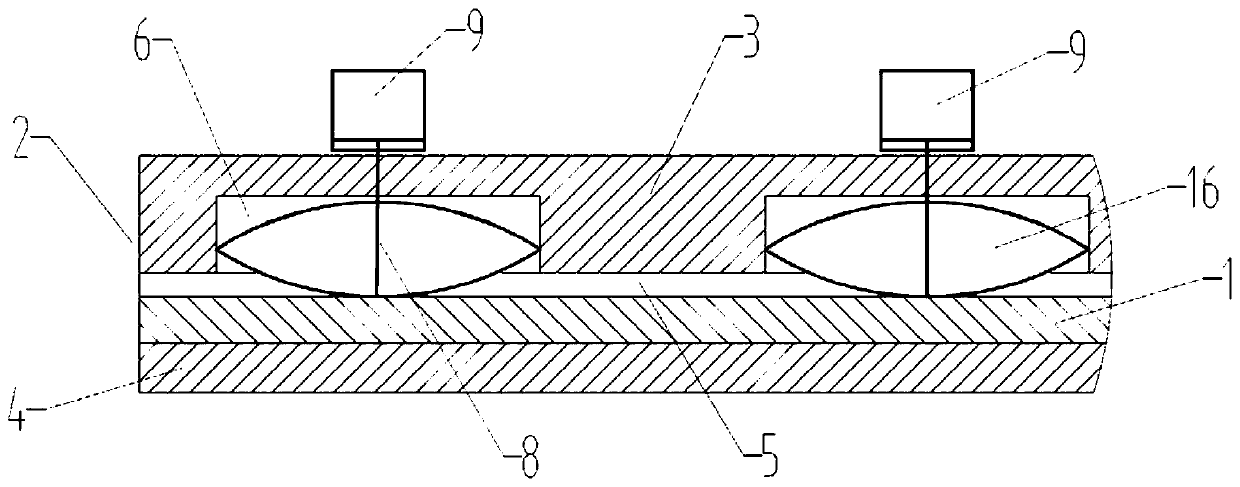
[0033] refer to Figure 5 , the tray 2 includes a Π-shaped main body 3, the lower end of the main body 3 is provided with an inwardly bent bent portion 4, and the main body 3 and the bent portion 4 are surrounded by a shape for the pressed plate 1 to move in and out. The cavity 5. In this embodiment, the cavity 5 is a regular rectangle, and of course it can also be of a different shape, such as an arc.

[0034] The first mounting groove 6 is arranged on the tray 2, and its groove opening faces the cavity 5; the second mounting groove 10 is arranged on the pressing plate 1, and the groove opening of the second mounting groove 10 faces the cavity. The groove opening of the first mounting groove 6 is described above.

[0035] The abutting assembly has a connecting piece 7 that extends out of...

Embodiment 2

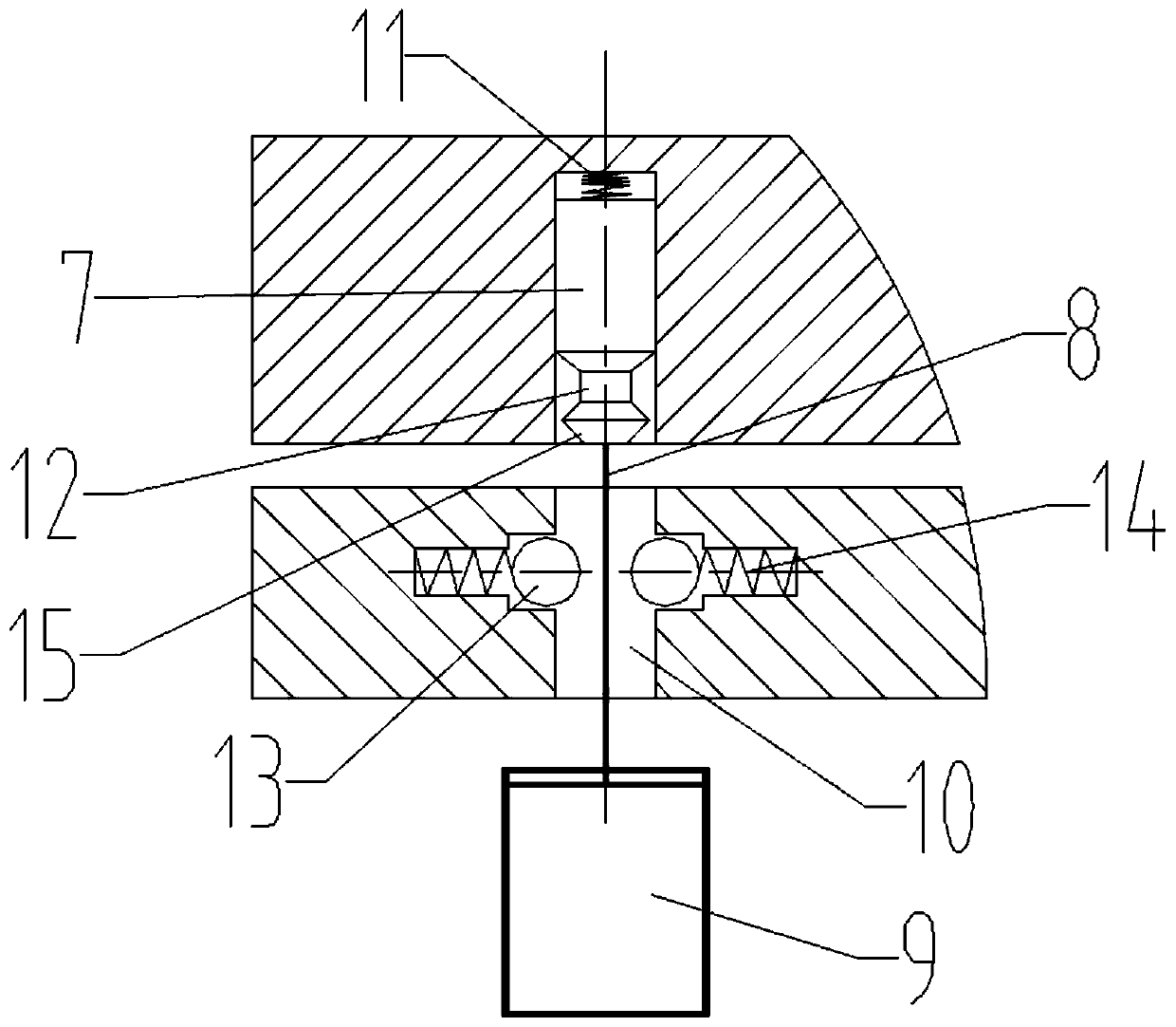
[0043] The locking platform in this embodiment, such as image 3 with Figure 4 As shown, the difference with Embodiment 1 is:

[0044] The first installation groove 6 is provided on the tray 2 , and its groove opening faces the cavity 5 . The abutting assembly has a connecting piece 7 that abuts against the pressing plate 1 after extending out of the first installation groove 6 in a free state, and the connecting piece 7 fixes the relative position of the tray 2 and the pressing plate 1 .

[0045] The connecting piece 7 is an elastic piece. Among them, because the disc spring 16 has the characteristics of large load, short stroke, small space required, convenient combination and use, easy maintenance and replacement, and high economical safety, therefore, in this embodiment, the disc spring 16 is used for the connecting part 7.

[0046] The tray 2 is provided with a through hole, and the unlocking assembly 9 has an output end 8 passing through the through hole of the tray...

Embodiment 3

[0049] The machine tool system in this embodiment has the locking platform in Embodiment 1 or Embodiment 2.

[0050] The pressing plate 1 and the unlocking assembly 9 of the locking platform are arranged on the machine tool, wherein the power source of the output end 8 of the locking assembly can be electric, pneumatic or hydraulic.


PUM


Abstract

The invention relates to the technical field of mechanism locking, in particular to a locking platform and a machine tool system. The locking platform comprises a pressing plate, a tray, a first installing groove, an abutting assembly and an unlocking assembly. The tray comprises an n-shaped body. An inward-bending bending part is arranged at the lower end of the body, and a cavity for the pressing plate to move in and move out is defined by the body and the bending part. The first installing groove is formed in one of the tray and the pressing plate, and a groove opening of the installing groove is arranged towards the cavity. The abutting assembly is provided with a connecting piece, wherein the connecting piece is connected with the other one of the tray and the pressing plate after stretching out of the first installing groove in the free state, and the connecting piece fixes the opposite position of the tray and the pressing plate. The unlocking assembly is provided with an outputend, wherein the output end stretches into the pressing plate or the tray to push the connecting piece into the first installing groove. The locking platform has the advantage of being safer.

Description

technical field [0001] The invention relates to the technical field of mechanism locking, in particular to a locking platform and a machine tool system. Background technique [0002] When the processing machine tool is working, the workbench on the processing machine tool is fixedly connected with the pallet on which the workpiece is installed, so as to ensure the safety and accuracy of workpiece processing during workpiece processing. In the prior art, a pneumatic or electric structure is usually used to fix the pallet to the workbench, that is, when the pallet is moved onto the workbench, a pneumatic or electric structure is used to fix the pallet to the workbench, and the workpiece is processed Finally, pneumatic or electric structural actions, instead of fixedly connecting the pallet and the workbench, the pallet can be separated from the workbench and moved out of the processing space of the processing machine. Since the existing technology uses pneumatic or electric s...

Claims


Application Information

Patent Timeline
IPC IPC(8): B23Q1/28
CPCB23Q1/28
Inventor 王子珺李恩东
Owner 北京优备加科技有限公司
Features
  • Generate Ideas
  • Intellectual Property
  • Life Sciences
  • Materials
  • Tech Scout
  • Unparalleled Data Quality
  • Higher Quality Content
  • 60% Fewer Hallucinations
Learn More