Intelligent electric vehicle charging device
A technology of car charging and charging piles, which is applied in the direction of electric vehicle charging technology, electric vehicles, charging stations, etc., can solve the problems of users' personal property loss, damage to public charging facilities, and affect normal charging, etc. And the effect of low cost and easy installation
- Summary
- Abstract
- Description
- Claims
- Application Information
AI Technical Summary
Problems solved by technology
Method used
Image
Examples
Embodiment 1
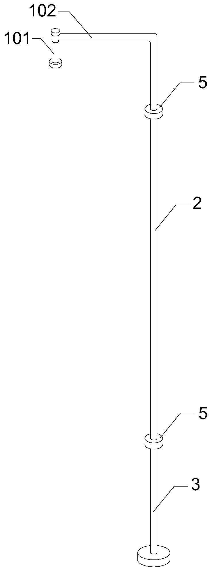
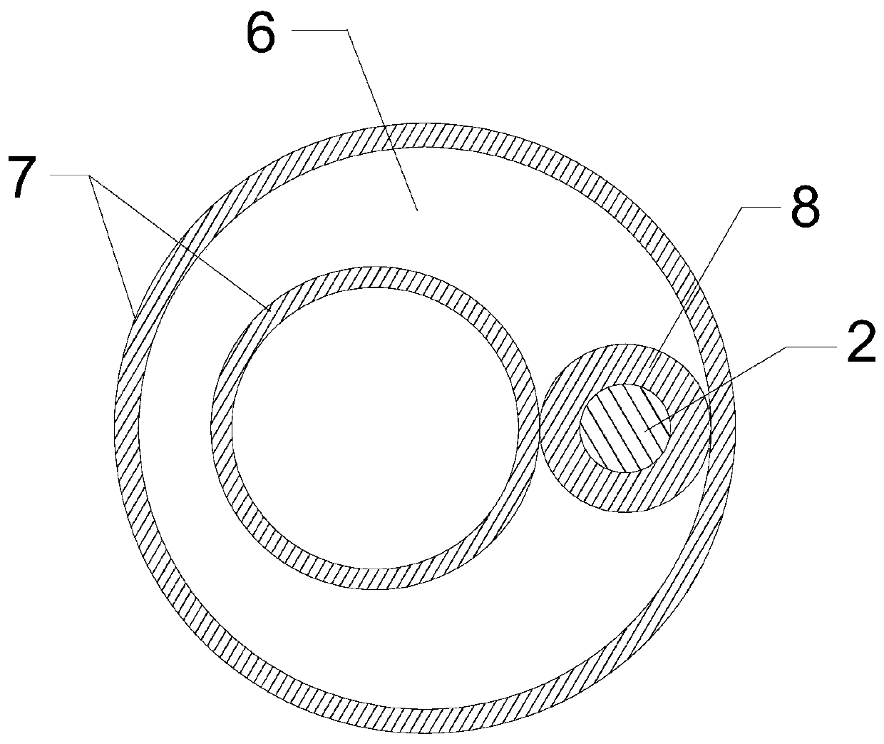
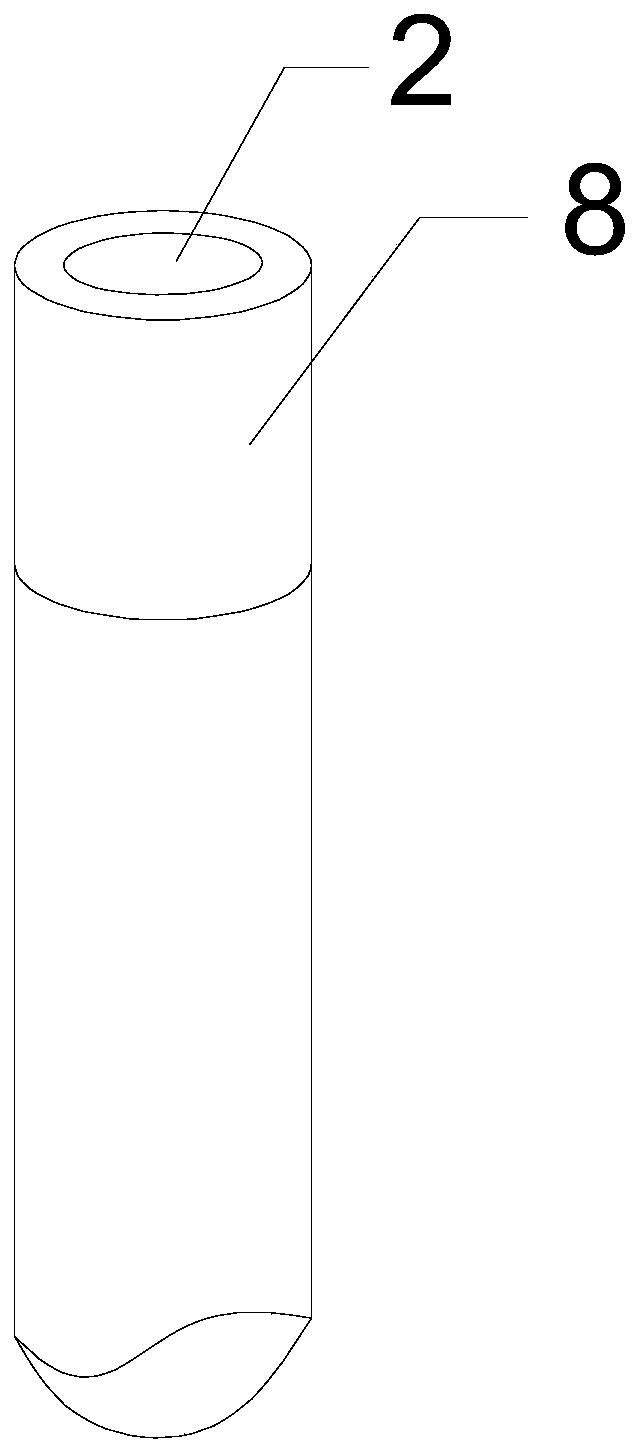
[0037] This embodiment provides an anti-collision structure for a car charging pile, such as Figures 1 to 4 As shown, it includes a connecting rod 1, a buffer rod 2 and a supporting rod 3; one end of the connecting rod 1 is used to connect with the top of the charging pile 4, and the other end is connected to one end of the buffer rod 2 through a buffer disc 5; one end of the supporting rod 3 The other end of the buffer rod 2 is connected with the buffer disc 5, and the other end is used for pressing contact with the ground; one end surface of the buffer disc 5 is integrated and fixedly connected with the connecting rod 1 or the support rod 3, and the buffer disc 5 is a disc structure. The other end surface of the buffer disc 5 is provided with an annular groove 6, and the annular groove 6 is composed of two sleeved eccentric cylinder walls 7; the two ends of the buffer rod 2 are provided with rubber buffer sleeves 8, and the two The end is inserted into the annular groove 6 ...
Embodiment 2
[0039] Further improvement on the basis of Embodiment 1, the connecting rod 1 includes a positioning rod 101 and an L-shaped rotating rod 102; One end is rotationally connected; the other end of the L-shaped rotating rod 102 is connected to one end of the buffer rod 2 through the buffer disc 5; the positioning rod 101 and the L-shaped rotating rod 102 are connected to form an inverted U-shaped structure or a similar inverted U-shaped structure. The top of the positioning rod 101 extends coaxially with a positioning column 103; one end of the L-shaped rotating rod 102 is provided with a rotating ring sleeve 104, and the rotating ring sleeve 104 is sleeved on the positioning column 103; it also includes an end cover 105, an end cover 105 It is screwed to the end of the positioning post 103 , and the end surfaces of the two axial ends of the rotating ring 104 are respectively in contact with the lower end surface of the end cover 105 and the top end surface of the positioning rod ...
Embodiment 3
[0041] This embodiment provides a smart electric vehicle charging device, such as Figure 5 As shown, it includes charging pile 4, and also includes a kind of anti-collision structure for automobile charging pile provided by embodiment 2; one end of connecting rod 1 is connected with the top of charging pile 4, and the other end and one end of buffer rod 2 are buffered The disc 5 is connected; one end of the support rod 3 is connected to the other end of the buffer rod 2 through the buffer disc 5, and the other end is in contact with the ground; the top end of the charging pile 4 is provided with a flange mounting chassis 9, and the end of the connecting rod 1 A flange-mounted top plate is provided, and the flange-mounted chassis 9 is threadedly connected with the flange-mounted top plate.
PUM
 Abstract
Description
Claims
Application Information
 - R&D
- Intellectual Property
- Life Sciences
- Materials
- Tech Scout
- Unparalleled Data Quality
- Higher Quality Content
- 60% Fewer Hallucinations
Browse by: Latest US Patents, China's latest patents, Technical Efficacy Thesaurus, Application Domain, Technology Topic, Popular Technical Reports.
© 2025 PatSnap. All rights reserved.Legal|Privacy policy|Modern Slavery Act Transparency Statement|Sitemap|About US| Contact US: help@patsnap.com


