
A retractable wing mechanism with slotted flaps and continuously variable wingspan

A technology of retractable aircraft and flaps, applied in the direction of wings, wing adjustments, aircraft parts, etc., can solve the problem that the wings cannot meet the requirements, reduce induced resistance and airfoil resistance, reduce lift-induced resistance, and reduce friction The effect of resistance

Active Publication Date: 2020-11-24
ZHEJIANG UNIV
View PDF8 Cites 0 Cited by
  • Summary
  • Abstract
  • Description
  • Claims
  • Application Information

AI Technical Summary

Problems solved by technology

At this time, the wing with a single aerodynamic layout can no longer meet the design requirements of this type of aircraft

Method used


Image

  • A retractable wing mechanism with slotted flaps and continuously variable wingspan
  • A retractable wing mechanism with slotted flaps and continuously variable wingspan
  • A retractable wing mechanism with slotted flaps and continuously variable wingspan

Examples


Embodiment Construction

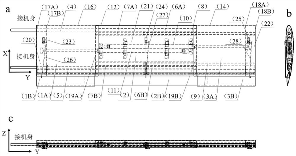
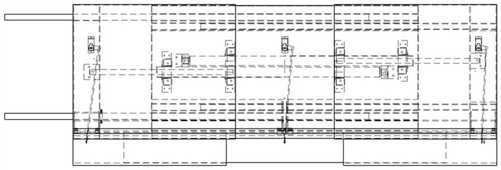
[0039] The purpose of the present invention is to provide a set of mechanisms for changing the length of the wings by stretching and retracting, and changing the curvature of the airfoil by retracting and retracting the flaps, so that the aircraft equipped with the wings can have good high-speed and low-speed performance. The detailed description is combined with the abstract drawings and Figure 1~6 illustrate.

[0040] The wing is a three-stage retractable wing mechanism, and each section of the wing includes a main wing and a flap. It specifically includes the inner main wing 1A; the outer main wing 3A; the middle main wing 2A nested between the inner main wing 1A and the outer main wing 3A; the inner flap 1B hinged with the inner main wing 1A; and the outer main wing 3A hinged The outer flap 3B of the outer section; the middle section flap 2B nested between the inner section flap 1B and the outer section flap 3B and hinged with the middle section main wing 2A; respectivel...


PUM


Abstract

The invention discloses a telescopic wing mechanism with slotted flaps and continuously variable wingspan. The inner main wing; the outer main wing; the middle main wing nested between the inner and outer main wings; the inner, middle and outer flaps respectively connected with the inner, middle and outer main wings; respectively used to drive the outer main wing, The first and second linear motors of the middle and outer main wings move along the span direction; the inner, middle and outer flap control servos are composed; one end of the inner wing front beam and rear beam is connected to the fuselage, and the other end is inserted into the middle wing Front and rear beams. The front and rear spars of the outer wing are inserted into the front and rear spars of the middle wing. The middle section flap is nested between the inner and outer section flaps. The front and rear beams of each section of the wing are placed in parallel along the span direction, and the main wings of the three sections of the wing all move telescopically along the direction of the front and rear beams, and at the same time drive the three sections of flaps to realize the telescopic movement. Telescopic positioning is realized by the internal locking mechanism of the linear motor. The flaps are controlled by three servos. The aerodynamic loads of the wing are transferred from the skin to the spar via the ribs.

Description

technical field [0001] The invention belongs to the field of aircraft design and technology, and in particular relates to a telescopic wing structure with slotted flaps and continuously variable wingspan applied to a fixed-wing aircraft. Background technique [0002] Traditional aircraft mostly use a single wing aerodynamic layout to meet the aerodynamic requirements of their main mission conditions. However, some aircraft need to meet multi-mission conditions (such as taking into account high-speed cruise control and low-speed task cruise). At this moment, the wing of single aerodynamic layout can no longer adapt to the requirements of this type of aircraft design. This requires a wing design that can change its aerodynamic shape according to the requirements of the flight mission and take into account different speed requirements. For low Mach number (speed less than 300 km / h) flight conditions, changing the span of the wing and changing the camber of the airfoil by lowe...

Claims


Application Information

Patent Timeline
Patent Type & Authority Patents(China)
IPC IPC(8): B64C3/18B64C3/26B64C3/28B64C3/54B64C9/06
CPCB64C3/182B64C3/26B64C3/28B64C3/54B64C9/06
Inventor 朱灶旭季廷炜谢芳芳郑耀
Owner ZHEJIANG UNIV
Learn More