A hydraulic safety valve group for a riser tensioner

A riser tensioner and safety valve technology, which is applied in the field of offshore oil drilling, can solve problems such as insufficient functions and easily lead to serious consequences, and achieve the effects of compact structure, high degree of equipment automation, and high system reliability.

Active Publication Date: 2017-02-01
BAOJI PETROLEUM MASCH CO LTD +2
View PDF6 Cites 0 Cited by
  • Summary
  • Abstract
  • Description
  • Claims
  • Application Information

AI Technical Summary

Problems solved by technology

[0005] The purpose of the present invention is to provide a hydraulic safety valve group of a riser tensioner, which solves the problem that the hydraulic safety valve of the tensioner in the prior art has insufficient functions to deal with special situations and easily leads to serious consequences

Method used


Image

  • A hydraulic safety valve group for a riser tensioner
  • A hydraulic safety valve group for a riser tensioner
  • A hydraulic safety valve group for a riser tensioner

Examples


Embodiment Construction

[0020] The present invention will be described in detail below in conjunction with the accompanying drawings and specific embodiments.

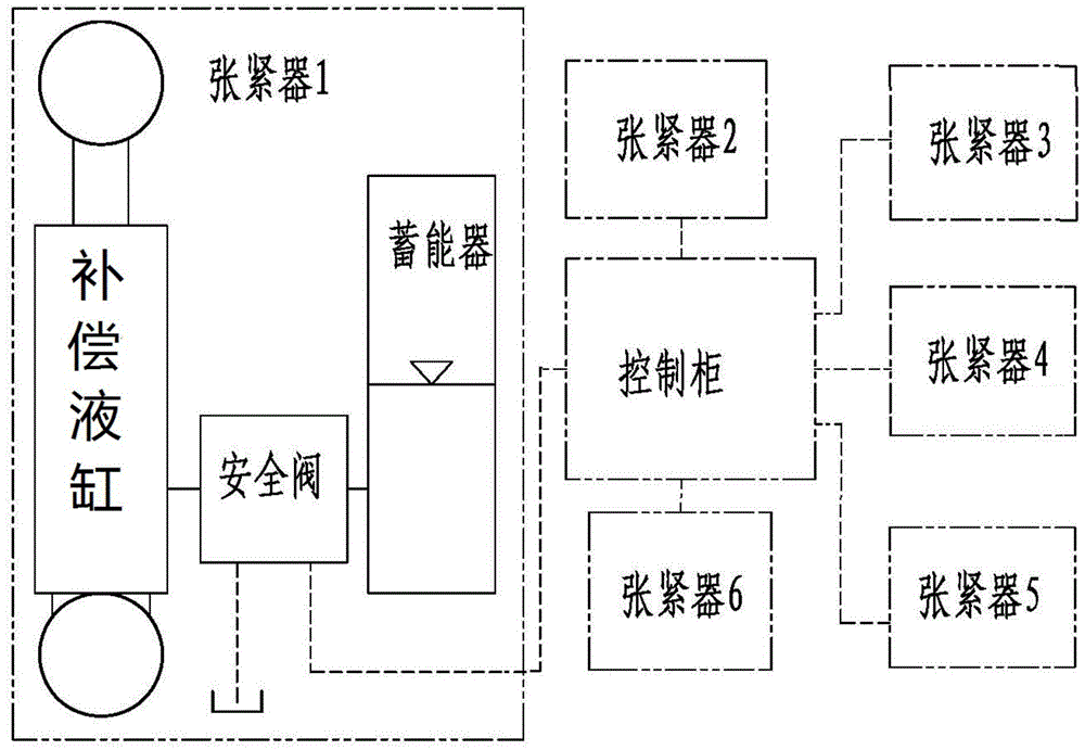
[0021] Such as figure 1 , the existing typical tensioner system is composed of 6 groups of tensioners, which are respectively connected with the control cabinet. Each group of tensioners is composed of compensation cylinder, safety valve and accumulator. The compensation cylinder and The heave movement of the platform is compensated by exchanging hydraulic oil between the accumulators, and the safety valve performs preset pressure control.

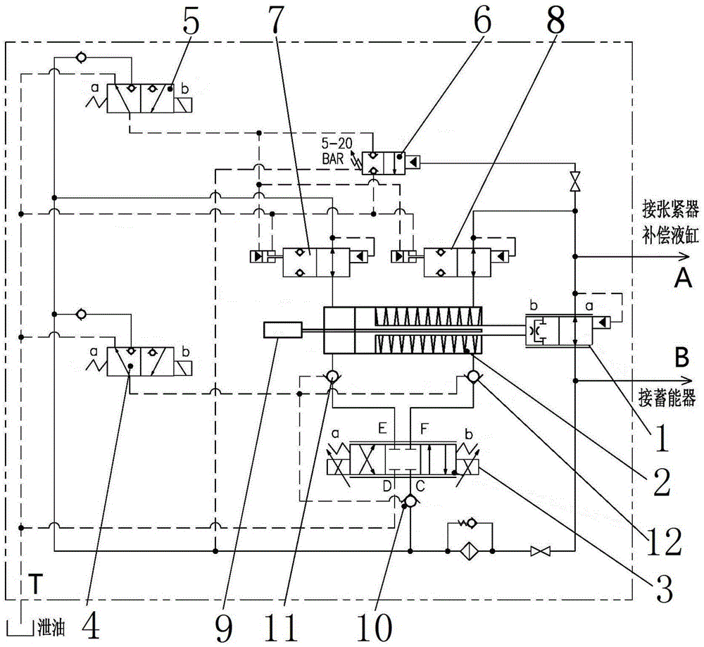
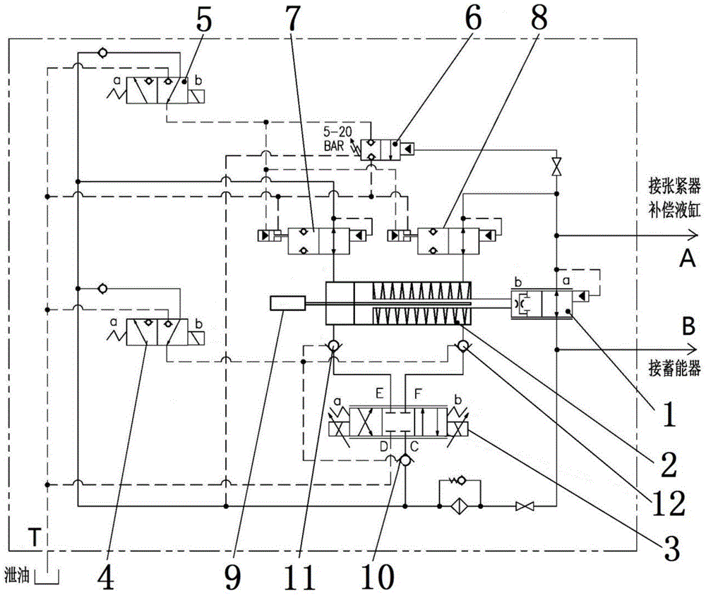
[0022] The safety valve group of the present invention is installed between the accumulator and the compensating fluid cylinder as a flow control valve.

[0023] refer to figure 2 , image 3 , the structure of the present invention includes a main valve 1, the main valve 1 communicates with the tensioner compensation cylinder through the A oil port, the main valve 1 communicates with the accumulator t...


PUM


Abstract

The invention discloses a riser tensioner hydraulic relief valve bank which comprises a main valve. A valve element of the main valve is in transmission connection with the front end of a piston rod of a control oil cylinder, the tail end of the piston rod of the control oil cylinder is connected with a linear displacement sensor, two oil cavities of the control oil cylinder are communicated with a proportional directional valve through a hydraulic control one-way II and a hydraulic control one-way III, and the proportional directional valve is connected back to the main valve through the other hydraulic control one-way I. The two oil cavities of the control oil cylinder are further communicated with a hydraulic control pilot-operated type stop valve, a solenoid valve II and a solenoid valve I through a hydraulic control reversing valve I and a hydraulic control reversing valve II, and the hydraulic control one-way I, the hydraulic control one-way II and the hydraulic control one-way III are further simultaneously communicated with the solenoid valve I. In addition, the proportional directional valve, the two solenoid valves and the two hydraulic control reversing valves are communicated with an oil drainage port through pipelines respectively. The riser tensioner hydraulic relief valve bank is simple in structure and reliable in function.

Description

technical field [0001] The invention belongs to the technical field of offshore oil drilling and is used for ensuring the safety of a riser system, and relates to a hydraulic safety valve group of a riser tensioner. Background technique [0002] The semi-submersible offshore platform is affected by waves and moves up and down. During the drilling operation, the relative position of the riser and the underwater wellhead equipment is required to remain unchanged. Riser tensioners are often used to offset the heave movement of the platform. impact. [0003] Riser tensioners are divided into two types: hydraulic cylinder direct drive type and wire rope type. The implementation methods of the two methods are different, but the principle is the same. However, due to the particularity of marine operations on semi-submersible offshore drilling platforms, the safety requirements for the riser system are extremely high, and the riser tensioner bears the weight of the entire riser sys...

Claims


Application Information

Patent Timeline
Patent Type & Authority Patents(China)
IPC IPC(8): F15B20/00F15B1/02F15B13/02F15B13/16E21B19/00
CPCE21B19/00F15B1/02F15B13/02F15B13/16F15B20/00F15B2201/00
Inventor 李欢冯文龙徐晓鹏李鹏雷静希
Owner BAOJI PETROLEUM MASCH CO LTD
Why Eureka
Try Eureka