Hydraulic lifting machine

A lift and hydraulic technology, which is applied in the field of hydraulic lifts, can solve the problems of the operator's troubles in the operation process and the limitation of the maximum height of the slide table.

Pending Publication Date: 2020-05-19
太仓成铭液压机械有限公司
View PDF0 Cites 0 Cited by
  • Summary
  • Abstract
  • Description
  • Claims
  • Application Information

AI Technical Summary

Problems solved by technology

[0003] But, according to the prior art, the maximum height of the rise of the slide table is limited
When the highest position of the slide table has certain limitations, it may cause some troubles for the operator during the operation

Method used


Image

  • Hydraulic lifting machine
  • Hydraulic lifting machine
  • Hydraulic lifting machine

Examples


Embodiment Construction

[0024] The technical solutions in the embodiments of the present invention will be clearly and completely described below in conjunction with the accompanying drawings in the embodiments of the present invention. Obviously, the described embodiments are only a part of the embodiments of the present invention, rather than all the embodiments. Based on the embodiments of the present invention, all other embodiments obtained by those of ordinary skill in the art without creative work shall fall within the protection scope of the present invention.

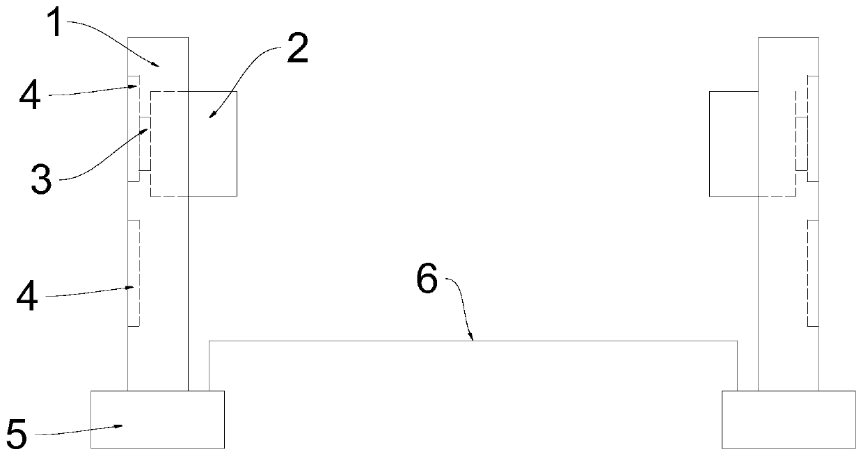
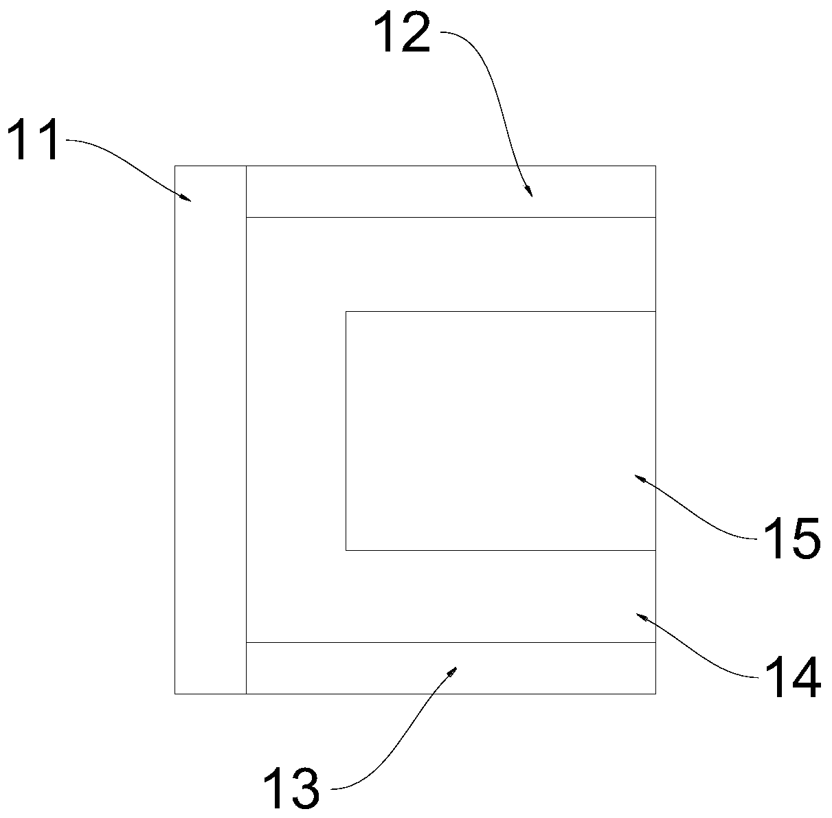
[0025] Reference figure 1 As shown, the embodiment of the present application discloses a hydraulic lift, including: a column 1, the column 1 includes a longitudinal beam and a top plate 14 arranged at the upper end of the longitudinal beam; a sliding table 2, the sliding table 2 can be vertically It is arranged on the longitudinal beam to move in a straight direction; wherein the top plate 14 is provided with a through hole 15 for the sl...


PUM


Abstract

The invention provides a hydraulic lifting machine. The hydraulic lifting machine comprises a stand column and a sliding table, wherein the stand column comprises a longitudinal beam and a top plate arranged at the upper end of the longitudinal beam, the sliding table can be movably arranged on the longitudinal beam in the vertical direction, and a through hole for allowing the sliding table to penetrate out is formed in the top plate; the longitudinal beam comprises a first side wall, a second side wall and a third side wall, the second side wall and a third side wall are arranged on the front side and the rear side of the side wall respectively, a groove is formed among the first side wall, the second side wall and the third side wall, and the top plate seals the groove at the top of thelongitudinal beam; the sliding table is arranged in the groove, a rack is arranged on the stand column, and a safety strip corresponding to the rack is arranged on the sliding table. By means of themechanism, the sliding table can penetrate out of the through hole of the top plate in upward moving process, thus, the highest limit position of the sliding table is no longer limited by the top plate of the stand column, meanwhile, the height of the stand column is not increased, and therefore the overall strength of the stand column is not affected.

Description

Technical field [0001] The invention relates to a hydraulic lifting component, a hydraulic lifting machine. Background technique [0002] The hydraulic lift for automobile maintenance is a special mechanical lifting equipment commonly used by large-tonnage automobile or truck repair and maintenance units. Generally speaking, a hydraulic elevator for automobile maintenance includes two oppositely arranged uprights, a base respectively arranged under the two uprights, and a connecting plate arranged between the bases. Two sliding tables which can move in the vertical direction are respectively arranged on the uprights. [0003] However, according to the prior art, the maximum height of the sliding table is limited. When the highest position of the sliding table has certain limitations, it may cause some confusion for the operator during the operation. After all, for large vehicles or some other special situations, the operator may want the vehicle placed on the sliding table to be...

Claims


Application Information

Patent Timeline
Patent Type & Authority Applications(China)
IPC IPC(8): B66F7/20B66F7/28
CPCB66F7/20B66F7/28
Inventor 王学荣
Owner 太仓成铭液压机械有限公司
Why Eureka
Try Eureka